V4730C/V8730C/V4734C 1:1 Gas/Air Servo Regulated Gas Valves
EN2R-9074 0612R1-NE 15
OPERATION
The V4730C/V8730C/V4734C are normally closed valves. The
valves open when energized and close when power is removed.
1. Do not put the system into service until you have satisfactorily
completed the Valve Leak Test, all applicable tests described
in the Checkout section of the instructions for the flame safe-
guard control, and any other tests required by the burner ma-
nufacturer.
2. All tests must be performed by a trained, experienced, flame
safeguard technician.
3. Close all manual fuel shutoff valves immediately if trouble oc-
curs.
After the installation is complete, cycle the valve several times
with the manual fuel shutoff valve cock closed. Make sure the val-
ve functions properly. Also, perform the Valve Leak Test before
putting the valve into service.
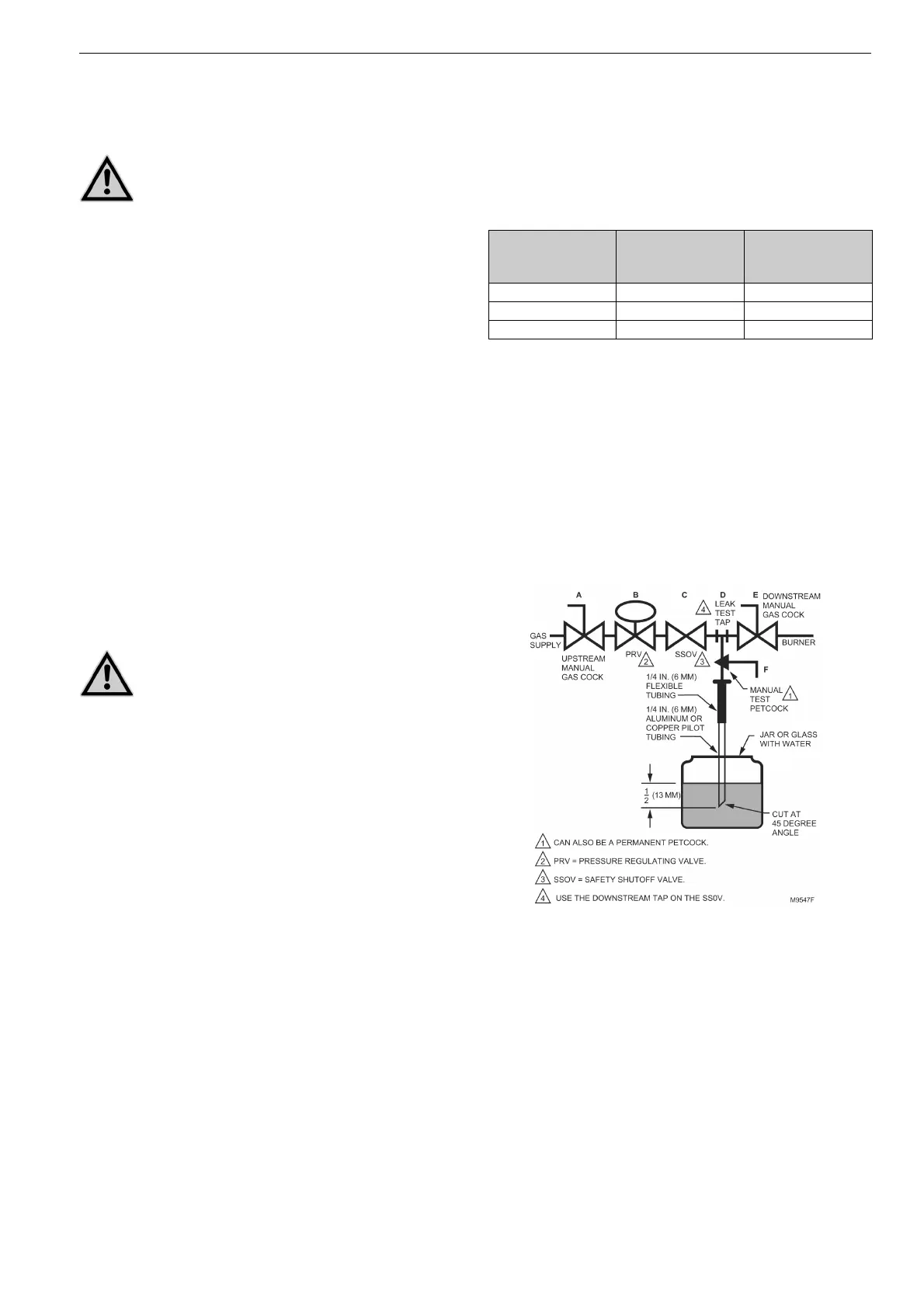
Valve Leak Test (Fig. 19)
This is a test for checking the closure tightness of the gas shutoff
valve. It should be performed only by trained, experienced, flame
safeguard technicians during the initial startup of the burner sys-
tem or whenever the valve is replaced. It is recommended that
this test should also be included in the scheduled inspection and
maintenance procedures. For a periodic inspection test, follow
steps 1, 3, 4, 5, 8, 9, 10, 12, 13, 17, and 18.
1. De-energize the control system to make sure no power goes
to the valves.
2. Close the upstream manual gas cock (A).
3. Make sure the manual test petcock (F) is closed in the leak
test tap assembly.
4. To test the first SSOV, remove the 1/8 in. (3mm) NPT plug
from pressure tap point P.
5. Install the leak test tap into pressure tap point P on the valve
body.
6. Open the upstream manual gas cock (A) to repressurize the
first SSOV.
7. Immerse the 1/4 in. (6 mm) tube vertically 1/2 in. (13 mm) in
a jar of water.
8. Slowly open the manual test petcock (F).
9. When the rate of bubbles coming through the water stabili-
zes, count the number of bubbles appearing during a ten-se-
cond period. Each bubble appearing represents a flow rate of
0.001 cfh (28 cch). See Table 4.
10. Close the upstream manual gas cock (A).
11. Remove the leak test tap from the valve body.
12. Using a small amount of pipe sealant on the 1/8 in. (3 mm)
NPT plug, reinstall the plug in pressure tap point P
13. To test the second SSOV, remove the 1/8 in. (3 mm) NPT
plug from the flange pressure tap point 4.
14. Install the leak test tap into pressure tap point 4.
15. Close the downstream manual gas cock (E).
16. Energize the first SSOV
Table 4: max. bubbles per pipe size
17. Immerse the 1/4 in. (6 mm) tube vertically 1/2 in. (13mm) into
a jar of water.
18. Slowly open the manual test petcock (F).
19. When the rate of bubbles coming through the water stabili-
zes, count the number of bubbles appearing during a ten-se-
cond period. Each bubble appearing during a 10-second
period represents a flow rate of 0.001 cfh (28 cch).
See Table 4.
20. De-energize First SSOV
21. Remove the leak test tap from the valve body.
22. Using a small amount of pipe sealant on the 1/8 in. (3 mm)
NPT plug, reinstall the plug in pressure tap point 4.
Fig. 19: Valve leak test
After the Test
1. . Make sure the downstream manual gas cock (E) is closed.
2. Open the upstream manual gas cock (A) and energize the
valve through the safety system.
3. Test with rich soap and water solution to make sure there is
no leak at the test tap (D) or any pipe adapter/valve mating
surfaces.
4. De-energize the valve (C).
5. Open the downstream manual gas cock (E).
6. Restore the system to normal operation.
WARNING
Explosion and Electrical Shock Hazard. Can cau-
se severe injury, death or property damage.
WARNING
Electrical Shock Hazard. Can cause severe injury
or death.
Remove the power from the system before beginning
the valve leak test to prevent electrical shock. More
than one disconnect may be involved.
Pipe Size (in. NPT) Maximum Seat
Leakage (UL)
Maximum Number
of Bubbles in 10
seconds
1/2 - 3/4 235 cch 6
1 275 cch 7
1 - 1/4 340 cch 8

 Loading...


