EasyManua.ls Logo

Honeywell V8730C - User Manual

Honeywell V8730C
16 pages
Print Icon
To Next Page IconTo Next Page
Loading...
Product data
EN2R-9074 0612R1-NE
V4730C/V8730C/V4734C
1:1 Gas/Air Servo Regulated Gas Valves
Note: Photo shows valve with manual safety shutoff valve and
venturi installed.
CONTENTS
Application ..........................................................1
Features ..............................................................1
Specifications ......................................................2
Ordering Information.............................................3
Installation ..........................................................13
Electrical Connections ........................................14
Adjustments and Final Checkout ........................14
Operation ...........................................................15
Troubleshooting..................................................16
Service Information ............................................16
APPLICATION
The V4730C/V8730C/V4734C 1:1 Gas/Air Servo Regulated Gas
Valves, with the addition of the Venturi Mixing Unit (VMU) and dc
fan, are used for modulating premix appliances such as gas bur-
ners, gas boilers, rooftop units, makeup air units and process ap-
plications.
FEATURES
Wide modulation range (14% to 100% of burner load).
24 Vac and 120 Vac models.
Main valve body with two shutoff seats (double block valve).
Closing time less than one second.
Mesh screen (strainer) between inlet flange and main body.
Various pressure tap points available at main body when no
additional valves or pressure switches are used.
DIN 43650 Plug Connector with 36-in. (914 mm) leadwires
included.
Flexible mounting positions of venturi manifold to fan.
Replaceable pipe flange adapters available.
Position indication lamp for each valve stage
Question and Answer IconNeed help?

Do you have a question about the Honeywell V8730C and is the answer not in the manual?

Overview

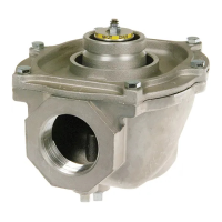
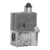
The Honeywell V4730C/V8730C/V4734C 1:1 Gas/Air Servo Regulated Gas Valves are designed for modulating premix appliances. These include gas burners, gas boilers, rooftop units, makeup air units, and various process applications. The valves operate in conjunction with a Venturi Mixing Unit (VMU) and a DC fan to achieve precise gas and air regulation.

Function Description

These valves are normally closed and open when energized, closing when power is removed. They provide a wide modulation range, from 14% to 100% of the burner load, ensuring efficient operation across various firing rates. The main valve body features two shutoff seats, functioning as a double block valve, and boasts a closing time of less than one second for enhanced safety. A mesh screen (strainer) is integrated between the inlet flange and the main body, meeting EN161 requirements for strainers, to prevent debris from entering the system. Various pressure tap points are available on the main body for pressure measurement or the installation of pressure switches, even without additional valves or switches. Each valve stage is equipped with a position indication lamp for easy monitoring.

Important Technical Specifications

  • Models: Available in 1/2 in., 3/4 in., 1 in., and 1-1/4 in. sizes.
  • Voltage/Frequency:
    • V4730C/V4734C models: 120 Vac, 50/60 Hz.
    • V8730C models: 24 Vac, 50/60 Hz.
  • Current Consumption (V1 + V2 Total Current):
    • 1/2 in. and 3/4 in. (120 Vac): 0.32 A.
    • 1 in. (120 Vac): 0.5 A.
    • 1-1/4 in. (120 Vac): 2.6 A at start, 1.04 A during operation (V4734C).
    • 1/2 in. and 3/4 in. (24 Vac): 1.56 A.
    • 1 in. and 1-1/4 in. (24 Vac): 1.72 A.
  • Capacity (Natural Gas 0.64 sp.gr):
    • 1/2 in.: 22-150 kW (73-512 kBtuh).
    • 3/4 in.: 43-300 kW (146-1024 kBtuh).
    • 1 in.: 55-382 kW (185-1300 kBtuh).
    • 1-1/4 in.: 55-382 kW (185-1300 kBtuh) or 97-680 kW (326-2287 kBtuh) when used with VMU680 unit.
  • Maximum Operating Pressure (UL):
    • 1.45 psi (100 mBar) for 1/2 in., 3/4 in., 1 in. (120V), and 1-1/4 in. (120V).
    • 1 psi (70 mBar) for 1-1/4 in. (24V).
    • CSA Approved: 0.5 psi (34 mBar), certified to 1/2 psi.
  • Connections: 1/8 in. (3 mm) NPT pressure taps at inlet and outlet flanges. Eight flange connections for pressure switches or Valve Proving System (VPS). Pipe connections meet EN151, Group 2 requirements.
  • Electrical Equipment: Standard DIN plug connector with 36-in. (914 mm) leadwires.
  • Ambient Temperature Range: 5°F to 140°F (-15°C to +60°C).
  • Coil Insulation Solenoid Valves: Class H insulation system.
  • Body Material: Aluminum alloy, die-cast.
  • Seals and Gaskets: Hydrocarbon-resistant NBR and Viton rubber types.
  • Opening Time:
    • Dead time maximum: 1 second.
    • First valve opening: less than 1 second.
    • Second valve opening: reaches 50% of adjustable outlet pressure within 5 seconds.
  • Maximum Allowable Leakage:
    • Outerwall: 3 cu. in./hr (50 cm3/h) at 0.87 psi (6 mBar) and 7.83 psi (540 mBar).
    • First Valve: 2.5 cu. in./hr (40 cm3/h) at 0.87 psi (6 mBar) and 7.83 psi (540 mBar).
    • Second Valve: 2.4 cu. in./hr (40 cm3/h) at 0.87 psi (6 mBar) and 7.83 psi (540 mBar).
  • High Pressure Test: Withstands 21.75 psi (1.5 Bar) inlet pressure in the OFF condition without damage.
  • Operational Voltage Range: Functions satisfactorily between 85% and 110% of rated voltage.
  • Minimum Load: 14-17% of reference load, equivalent to a minimum pressure differential of 0.2 in. wc (50 Pa) of the 1:1 venturi/servo regulator gas control.
  • Approvals: Gas Appliance Directive 90.396/EEC, ANSI: Z21.21, CSA: 6.5.

Usage Features

The valves are designed for flexible installation. While factory-calibrated for upright mounting, they can be mounted up to ±90 degrees from this position without significantly affecting fuel/air metering at medium and high firing rates. For lower firing rates, a field adjustment of the low fire gas flow can compensate for non-upright mounting. The venturi manifold can be mounted in flexible positions relative to the fan. Replaceable pipe flange adapters are available for convenience. The included DIN 43650 Plug Connector with 36-inch leadwires simplifies electrical connections.

Maintenance Features

The fine mesh strainer (0.135 in. [0.34 mm] diameter) is serviceable and can be cleaned or replaced after removing the inlet flange screws. Flange kits, including a flange with sealing plug, an O-ring, and screws, are available for maintenance. Manual shut-off valve kits are also available for different valve sizes. The manual provides detailed instructions for a comprehensive Valve Leak Test, which is crucial for initial startup, valve replacement, and periodic inspections. Troubleshooting procedures are outlined to diagnose issues such as the valve not opening or closing correctly, emphasizing safety precautions like disconnecting power and gas supply before any work. The screen/strainer replacement process is also clearly described, ensuring easy maintenance of this critical component.

Honeywell V8730C Specifications

General IconGeneral
BrandHoneywell
ModelV8730C
CategoryControl Unit
LanguageEnglish

Related product manuals