VC SERIES
Honeywell • All rights reserved EN0H-0327GE25 R0206
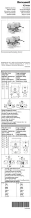
3-way diverter valve
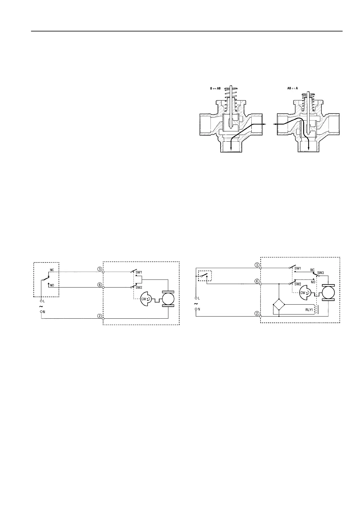
With an SPDT (3-wire) actuator
On a call for heat, the NO controller contacts close, the valve
closes port B and opens port A. When port A is in the fully
open position the cam closes limit switch SW1 and opens
limit switch SW2. When the need for heat is satisfied the NC
controller contacts close, energising the valve through SW1,
causing port A to close. When port A is fully closed the cam
closes SW2 and opens SW1. The valve is ready for the next
call for heat.
With an SPST (2-wire and common) actuator
On a call for heat the controller contacts close, RLY1 is ener-
gized making the NO contacts in switch SW3, causing port B
to close and port A to open. When port A reaches the fully
open position the cam closes switch SW1 and opens switch
SW2. When the need for heat is satisfied, the controller con-
tacts open. RLY1 is de-energized making the NC contacts in
SW3 and port A is driven closed through SW1 and the NC
contacts of SW3. When port A is in the fully closed position
the cam closes SW2 and opens SW1. The valve is ready for
the next call for heat.
For both types of actuator a power failure will leave the valve
at the position it was in when interrupted. When power is
restored, the valve will respond to controller demand.
Fig. 2. Fluid flow through 3-way VC valve
Wiring
Figures 3 and 4 show wiring connections for 2-way and 3-way
valves. Port A open and closed denotes valve open and clo-
sed for 2-way, and AB-A open and AB-B open for 3-way
valves respectively. A means for disconnection from the
supply having a contact separation of at least 3 mm in all
poles must be incorporated in the fixed wiring. On Molex™
connector models, actuator and auxiliary switch voltages
must be the same to meet the approval requirement. For
mixed voltages, the cable assembly version is recommended.
Fig. 3. Logic sequence diagram with 3-wire actuator for
SPDT contoller
Fig. 4. Logic sequence diagram with 2-wire + common
actuator for SPST contoller

 Loading...