VC SERIES
EN0H-0327GE25 R0206 6 Honeywell • All rights reserved
Installation
WARNING
Installer must be a trained, experienced service
person.
When installing this product:
• Read these instructions carefully. Failure to follow
them could damage the product or cause a hazardous
condition.
• Check the ratings given in the instructions and on the
product to make sure it is suitable for your
application.
• Always conduct a thorough checkout after installation.
CAUTION
• Disconnect power supply before wire connection to
prevent electrical shock and equipment damage.
• It is advisable to remove the actuator head from the
valve body for ease of installation. Fit the actuator
head in the most convenient position for wiring.
• On sweat fitted valves, the cartridge is shipped loose
or is removed to avoid being damaged during the sol-
der operation.
• On 24 V systems, never short circuit the valve coil
terminals. This may burn out the heat anticipator in
the thermostat.
• To remove the actuator head 25 mm clearance is
needed above the actuator.
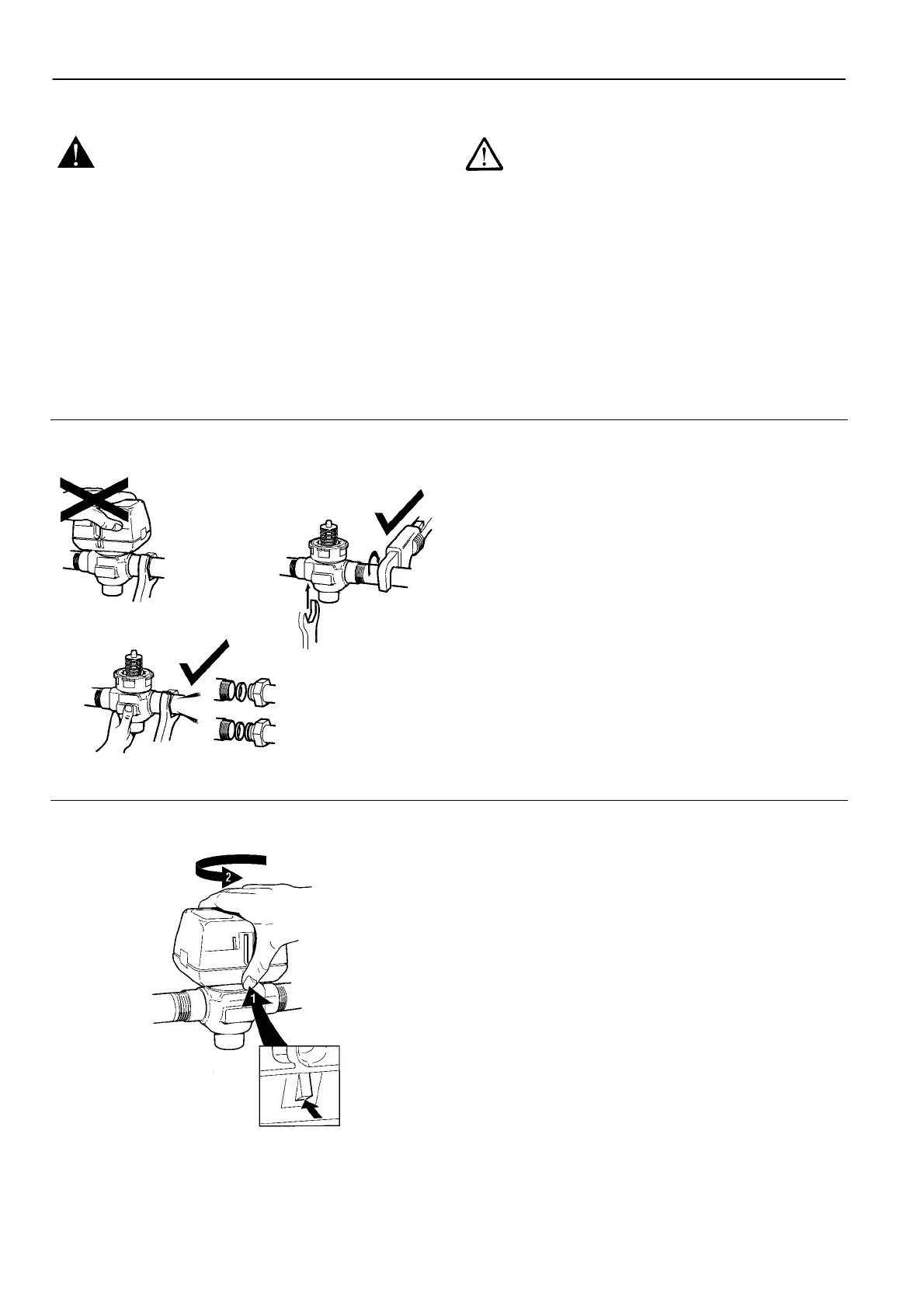
Plumbing
Fig. 7. Plumbing
The valve may be plumbed in any angle but preferably not
with the actuator head below the horizontal level of the valve
body. Make sure there is enough room around the actuator
head for servicing or replacement.
When used to form part of a central heating system, do not
locate it where it will block the system vent, cold feed or any
bypass when the valve is closed.
Mount the valve directly in the tube or pipe. Do not grip
actuator head while making and tightening plumbing
connections. Either hold valve body in your hand or attach
adjustable spanner across the hexagonal or flat faces on the
valve body.
Compression models
For compression fitted models, tighten the compression nuts
enough to make a watertight seal. Take care not to
overtighten.
To install a replacement actuator head
Fig. 8. Latch mechanism
Important
Installation of a new actuator head does not require draining
the system providing the valve body and cartridge assembly
remain in the pipeline.
1. Disconnect power supply before servicing to avoid electri-
cal shock or equipment damage.
2. Disconnect leadwires to actuator head, or depress tab on
Molex™
connector and remove. Where appropriate, label
wires for rewiring.
3. The actuator head is automatically latched to valve (see
figure 8). To remove, lift up on the latch mechanism lo-
cated directly below the red manual open lever. Press the
actuator head down towards the body with moderate hand
force and turn counter-clockwise by 1/8 turn (45 degrees)
simultaneously. Lift the actuator head off the valve body.
NOTE: Actuator can also be installed at right angles to valve
body but in this position latch mechanism is not engaged.
4. Install the new actuator head by reversing process in (3).
5. Reconnect leadwires or Molex™
connector.
6. Restore power.
 Loading...