VC SERIES
EN0H-0327GE25 R0206 2 Honeywell • All rights reserved
Specifications
Medium Water or water-glycol mixture
(max. 50% glycol content),
quality to VDI 2035
pH-value 8...9.5
Operating temperature 1...95°C (34...203°F)
120°C (248°F) short duration
peak
Ambient temperature max. 65°C (149°F)
Operating pressure max. 20 bar (290 psi) static
max. 100 bar (1,450 psi) burst
Differential pressure max. 4 bar (58 psi)
k
vs (cv)-values see chapter “Dimensions” below
Flow 2-way: flow can be in either
direction. When actuator is not
mounted valve is in closed
position
3-way: bottom port is marked
AB. End ports are marked A and
B. When actuator is not
mounted port A is closed.
Voltage 24 V, 50-60 Hz (blue label)
200-240 V, 50-60 Hz (red label)
Power consumption 4 VA
(when valve position changes)
Auxiliary switch rating 1.0 A @ 250 V, 50-60 Hz
(minimum 0.05 A @ 24 Vdc)
Nominal timing Valve opens in 7 seconds
(20% faster for 60 Hz)
Electrical termination 1. Molex™ socket: requires
mating connector,
alternatively
2. With integral 1 m leadwire
Shipping temperature -40…65°C (-40…149°F)
Humidity rating 5…95% RH (non-condensing)
Atmosphere non-corrosive, non-explosive
Function
VC Series 2-position hydronic valves are used in domestic
and small commercial applications to control the flow of hot
and/or cold water. They consist of an actuator, valve and a
cartridge assembly.All moving and sealing parts of the valve
are constructed in the cartridge assembly. The ports are
sealed with O-rings on the outer surface of the piston.
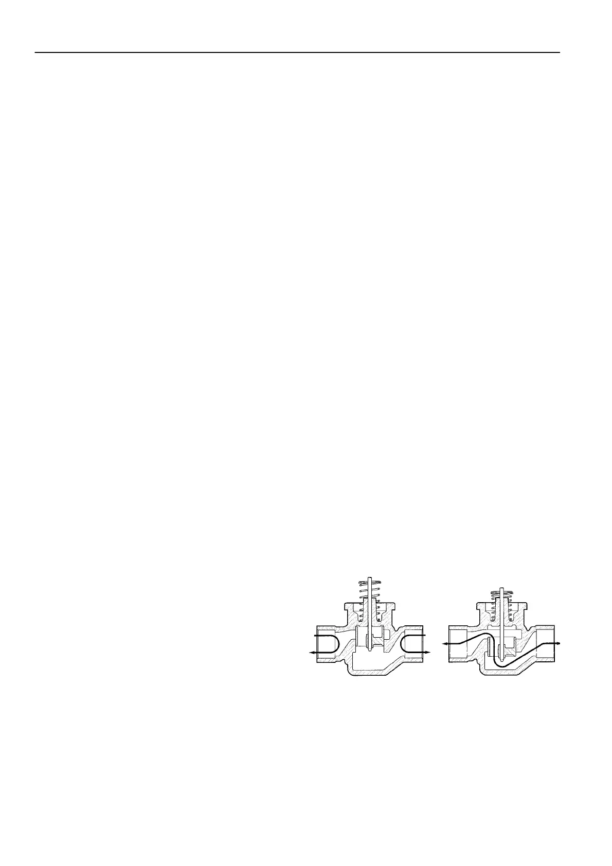
When the valve stem is driven down to open port A the water
will flow through the hollow piston to the other port. In case of
a 3-way valve with the piston driven down port B is sealed,
allowing flow between port AB and port A. With the stem up
the flow is between port AB and port B.
The valve family offers a variety of versions of pipe connecti-
ons to suit the different applications. The valve pressure loss
characteristic is dependent on the pipe connections/ dimensi-
ons. For the actual valve rating please refer to the specificati-
on section.
2-way valve
With an SPDT (3-wire) actuator
On a call for heat, the NO controller contacts close and the
valve opens. When the valve is fully open, the cam closes
switch SW1 and opens switch SW2. When the need for heat
is satisfied the NC controller contacts close, energising the
valve through SW1 and closing the valve. When the valve is
fully closed, the cam closes SW2 and opens SW1. The valve
is ready for the next call for heat.
With an SPST (2-wire and common) actuator
On a call for heat, the controller contacts close, RLY1 is e-
nergized making the NO contacts in switch SW3 causing the
valve to open. When the valve reaches the fully open position
the cam closes switch SW1 and opens switch SW2. When
the need for heat is satisfied, the controller contacts open,
RLY1 is de-energized and the valve motor is driven through
SW1 and the NC contacts of SW3. When the valve reaches
the fully closed position, the cam closes SW2 and opens
SW1. The valve is ready for the next call for heat.
For both types of actuator a power failure will leave the valve
at the position it was when interrupted. When power is resto-
red, the valve will respond to controller demand.
Fig. 1. Fluid flow through 2-way VC valve

 Loading...