25 EN2R-9004 0606R20-NE
ADJUSTMENTS AND CHECKOUT
IMPORTANTIMPORTANT
Adjustments must be made by qualified persons only.
If the appliance manufacturer supplies checkout and/
or service and maintenance instructions carefully fol-
low them. If these instructions are not provided then
use the procedure outlined below.
Pressure tap
The gas control is provided with a pressure tap of 9 mm outer
diameter at inlet and outlet side.
When checking the pressure undo the screw a half turn and
slip tube over nipple.
Ensure that screw is retightened after making test.
Pilot flame (VK4100/VK8100 only)
WARNING
It should be noted, that after a long time of stoppage
(summer) it can take up to 60 s to come to an ignition of
the pilot burner.
Outlet pressure adjustment on/off versions (see page 4 )
• Disconnect pressure feedback connection (if applicable)
• Start-up appliance in order to have gas input to burner.
• Check gas input to the appliance using a clocking gas
meter or alternatively a pressure gauge connected to the
outlet pressure tap.
• Remove cap screw to expose pressure regulator
adjustment screw.
• Slowly turn adjustment screw with a small screw driver until
the burner pressure required is recorded on the pressure
gauge. Turn adjustment screw clockwise to increase or
counter-clockwise to decrease gas pressure to the burner.
• For non-regulating mode (LP gas) turn adjustment screw
clockwise until it stops.
• Replace pressure regulator cap screw.
• Connect pressure feedback connection (if applicable).
Outlet pressure adjustment throttle versions VK.1..E/T(see page 4)
• Energize electric operators in order to have gas input to
burner.
• Check input to the appliance using a clocking gas meter or
alternatively a pressure gauge connected to the oultet
pressure tap.
• Turn the flow adjustment screw with a screw driver in
clockwise direction to decrease and turn counter
clockwise to increase the gas flow.
Check of
SOFTLITE
The SOFTLITE pressure is factory set.
Check burner performance at this pressure observing burner
ignition and flame characteristics. Burner should ignite
promptly and without flash back to orifice and all ports should
remain lit.
Cycle burner several times (wait 15 seconds between cycles
to allow servo system to resume slow open action).
Repeat check of slow opening after allowing the appliance to
cool down.
SOFTLITE adjustment (see page 4)
The
SOFTLITE pressure can be increased from the rated
SOFTLITE to optimise the ignition or to change over to another
gas type.
• Check the ignition as described above.
• Turn the appliance off.
• Remove the dust cap. This can be done by turning it 45
degrees counter-clockwise and then lifting off the dust cap
• Turn the adjustment screw one step in the direction ”MAX”
to increase or in the direction ”MIN” to decrease the
SOFTLITE pressure.
NOTE: Change over from natural gas to LP gas by turning
from mininimum to maximum.
• Start up the appliance and re check the ignition, and repeat
the adjustment if needed.
• Replace dust cap.
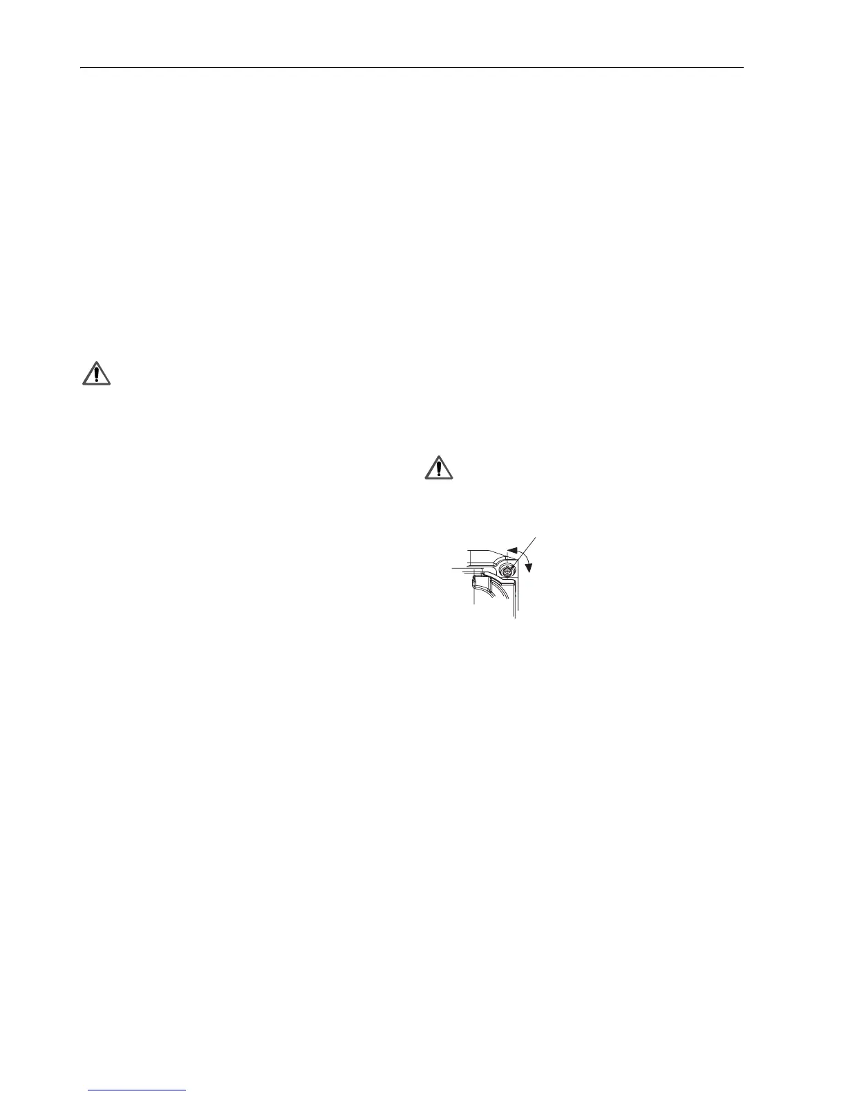
Throttle adjustment ..VE types.
The position of the throttle screw can be found on page 5.
Apply a screwdriver to turn the screw.
To decrease the flow, turn screw clockwise.
To increase flow, turn screw counter-clockwise.
WARNING
Applied torque may not exceed 8 Ncm
Final checkout of the installation
Set appliance in operation after any adjustment and observe
several complete cycles to ensure that all burner components
function correctly and that cap screw and cover are fitted and
secured.
Maintenance and service
Under normal circumstances no maintenance or service is
required.
Screws on the gas control that have been sealed must never
be removed.
Throttle scre
 Loading...


