HONEYWELL
HONEYWELLHONEYWELL
HONEYWELL
CLASS “A” COMBINATION VALVES
VQ400M-Series
EN2R9081-C
October 2009
11
ADJUSTMENTS AND FINAL
CHECKOUT
The procedures described in this chapter are
related to the adjustments on the main gas valve,
pilot valve and by-pass valve. For adjustments on
the other additional functionalities (e.g. pressure
switch), refer to the included instruction sheet of the
product in question in the package.
CAUTION
• Adjustments must be made by qualified
personnel only.
• To ensure a safe closing of the valves, it is
essential that voltage over the terminals of
operators is reduced to 0 Volts.
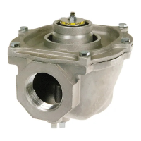
2
nd
main valve fast opening
Figure 9 Adjusting flow rate.
Flow rate adjustment (see Fig. 9.)
1. Remove the cap screw from top of the coil.
2. Place a socket head wrench into the
adjustment nut.
3. Turn wrench counter-clockwise to increase
or clockwise to decrease flow rate.
4. Replace cap screw.
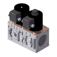
2
nd
main valve slow opening
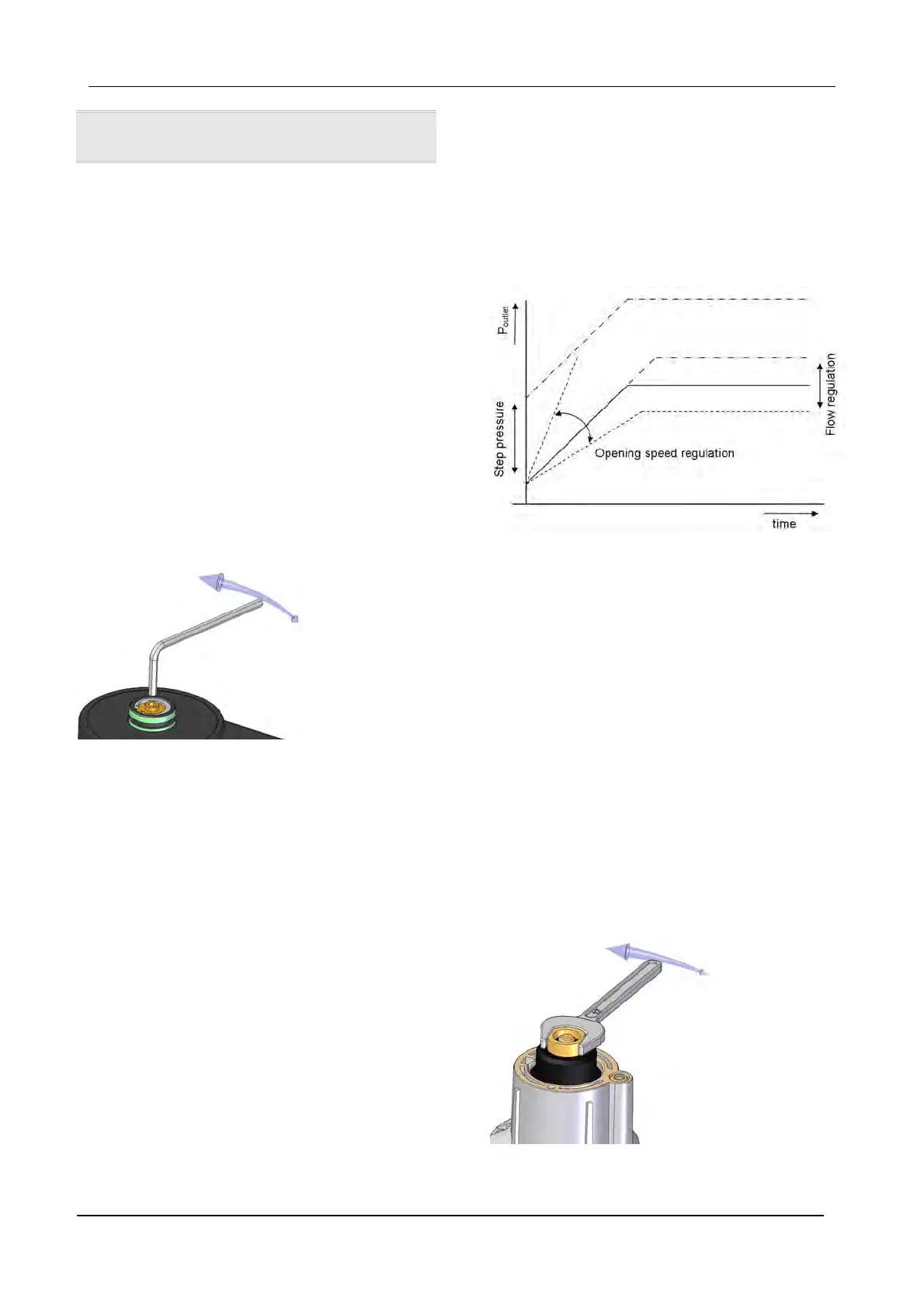
The following characteristics can be adjusted:
• flow rate
• step pressure
• opening speed
Figure 10 Characterized opening.
IMPORTANT
To ensure a satisfactory setting of the valve the
pressure drop over the valve should be at least
10% of the supply pressure or 2.5 mbar which ever
is the greatest.
Flow rate adjustment
1. Remove the cap from top of the coil by
loosening both screws.
2. Place a wrench on the adjustment hexagon
nut.
3. Turn wrench counter-clockwise to increase
or clockwise to decrease the flow rate.
4. Replace cap on top of the coil.
Figure 11 Adjusting flow rate.
 Loading...