HONEYWELL
HONEYWELLHONEYWELL
HONEYWELL
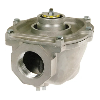
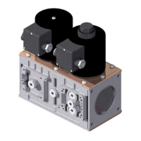
CLASS “A” COMBINATION VALVES
VQ400M-Series
EN2R9081-C
October 2009
2
CONTENTS
VQ400M SERIES ........................................................... 1
CLASS “A” COMBINATION VALVES ......................... 1
APPLICATION................................................................ 1
Contents ......................................................................... 2
FEATURES .................................................................... 2
DESCRIPTION............................................................... 3
SPECIFICATION ............................................................ 3
Models ........................................................................ 3
Dimensions ................................................................. 3
Pipe sizes.................................................................... 4
Capacity...................................................................... 4
Connections................................................................ 4
Torsion and bending stress......................................... 4
Supply voltages........................................................... 4
Electrical equipment.................................................... 4
Electrical connections ................................................. 5
Ambient temperature range ........................................ 5
Coil insulation solenoid valves .................................... 5
Enclosure.................................................................... 5
Body material.............................................................. 5
Closing spring ............................................................. 5
Valve plunger.............................................................. 5
Seals and gaskets....................................................... 5
Power consumption .................................................... 5
PERFORMANCE CHARACTERISTICS......................... 6
Opening time............................................................... 6
Closing time ................................................................ 6
Maximum working frequency ...................................... 6
Duty cycle ................................................................... 6
Operational voltage range........................................... 6
Designed life time ....................................................... 6
CAPACITY CURVES...................................................... 7
INSTALLATION.............................................................. 8
IMPORTANT............................................................... 8
WARNING................................................................... 8
Maintenance and service............................................ 8
Mounting position........................................................ 8
Mounting location........................................................ 8
Main gas connection flanged valves ........................... 9
WARNING!.................................................................. 9
Electrical connection................................................... 9
WARNING................................................................... 9
Wiring.......................................................................... 9
ADJUSTMENTS AND FINAL CHECKOUT .................. 11
CAUTION.................................................................. 11
2
nd
main valve fast opening....................................... 11
2
nd
main valve slow opening ..................................... 11
IMPORTANT............................................................. 11
Final checkout of the installation............................... 12
OPTION INSTALLATION ............................................. 13
WARNING................................................................. 13
CONSTRUCTION AND WORKING PRINCIPLES........ 13
ORDERING INFORMATION ........................................ 14
NOTE........................................................................ 14
Replacement of parts.................................................... 15
Warning..................................................................... 15
Recommended accessories ......................................... 15
APPROVALS................................................................ 17
Declaration of Conformity.......................................... 17
FEATURES
• Class “A” safety combination valve for
control of gaseous fluids in gas consuming
appliances in accordance with international
standards.
• Main body with two gas valves with single
seat.
• Possibility of installing internal by-pass
valve to achieve high-low flame control.
• Possibility of installing internal or external
pilot valve.
• Possibility of installing vent valve.
• Possibility of installing flanged minimum
and maximum pressure switches.
• Possibility of installing valve Proving
System (VPS).
• Possibility of mounting Closed Position
Indication switch (CPI) at bottom of safety
valve V1 and / or valve V2.
• Closing time: < 1 second.
• Coils field replaceable.
• Coils suitable for permanent energizing.
• Fine mesh screen between inlet flange and
main body (optional).
• Various pressure tap points at main body
available
• Second main valve, either with adjustable
flow regulator (fast), or characterized
opening mechanism (slow) with adjustable
maximum flow rate and step pressure.
• Rectifier boards field replaceable.
• PG11 cable strain relief standard at
VQ400M.
• Plug connector according to ISO 4400 /
DIN EN 175301-803 optional for VQ400M.
 Loading...