HONEYWELL
HONEYWELLHONEYWELL
HONEYWELL
CLASS “A” COMBINATION VALVES
VQ400M-Series
EN2R9081-C
October 2009
4
Pipe sizes
For connecting with several pipe sizes it is
recommended to mount Honeywell flange kits
which can be ordered separately as indicated
below.
Table 2 Overview of recommended pipe sizes.
Gas valve Recommended pipe size Option
VQ420M ½” 1
VQ420M ¾” 2
VQ425M 1”
VQ440M 1 ¼” 1
VQ440M 1 ½” 2
VQ450M 2”
Recommended flanges for each model to be
mounted are given in table 3 and table 4.
Capacity
Main body: see capacity curves at Figure .
Maximum operating pressure is 360 mbar for all
models
• 360 mbar
o VQ420M
o VQ425M
o VQ440M
o VQ450M
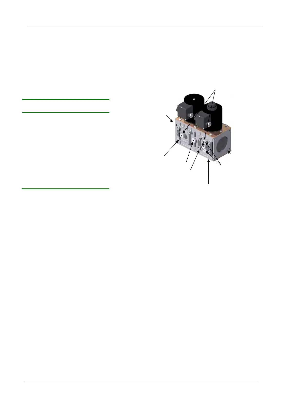
Connections
As shown in the figure below, VQ400M is provided
with plugs and flanges giving flexibility to customize
this combination valve with Honeywell accessories.
Figure 3 Interfaces for possible accessories
Torsion and bending stress
Pipe connections meet group 2 according to EN161
requirements.
Supply voltages
VQ400 M series can be ordered for line voltage:
• 230 Vac, 50/60 Hz
• 115 Vac, 50/60 Hz
• 120 Vac, 50/60 Hz
Electrical equipment
AC rectified coils with separated rectifier inside the
cover.
Plugs for mounting:
• pressure tap
• Valve proving
system
• Pressure switches
Plugs for connecting:
• By pass valve
• Internal or external
pilot valve
• Vent valve
Flange connection V2
In the bottom plate two
plugs are available for
mounting Closed
Outlet flange
Inlet flange
Flange connection V1
Plug for mounting
 Loading...