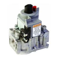
achieved by adjusting the gas control, check gas control
inlet pressure using a manometer at inlet pressure tap. If
inlet pressure is in the nominal range (refer to Table 5),
replace gas control. Otherwise, take the necessary steps
to provide proper gas pressure to the control.
VS820C,P; VS821C (Step-Opening Pressure Regulator)
1. Check the
full rate manifold pressure listed on the
appliance nameplate. Gas control
full rate outlet pressure
should match this rating.
2. With main burner operating, check gas control outlet
flow rate using the meter clocking method or outlet pres-
sure using a manometer connected to the outlet pressure
tap on the control. Refer to Fig. 3 or 4.
3. If necessary, adjust pressure regulator to match ap-
pliance rating. Refer to Table 5 for factory set nominal
outlet pressure and adjustment range.
a. Remove pressure regulator adjustment cap
screw.
b. Using screwdriver, turn inner adjustment screw
clockwise to increase or counterclockwise
to decrease gas pressure to burner.
c. Always replace cap screw and tighten firmly to
ensure system functions properly.
4. If desired outlet pressure or flow rate cannot be
achieved by adjusting the gas control, check gas control
inlet pressure using a manometer upstream of the gas
control. If inlet pressure is in the nominal range (refer to
Table 5), replace gas control. Otherwise, take the neces-
sary steps to provide proper gas pressure to the control.
5. Carefully check burner lightoff at
step pressure. Make
sure burner lights smoothly and without flashback to ori-
fice. Make sure all ports remain lit. Cycle burner several
times, allowing at least 30 sec. between cycles for regula-
tor to resume step function. Repeat after allowing burner
to cool. Readjust full rate outlet pressure if necessary to
improve lightoff characteristics.
IMPORTANT
The V5308 on the VS820D is not field adjustable.
The HI or LOW flame setting is selected by position-
ing the white knob on the regulator. Refer to Fig. 10.
Fig. 10—HI and LOW settings for VS820D.
1. Check the LOW flame setting listed on the appliance
nameplate. Gas control LOW flame setting should match
this rating.
2. With main burner operating, check gas control outlet
flow rate using the meter clocking method or outlet pressure
using a manometer connected to the outlet pressure tap on
the control. Refer to Fig. 3 or 4.
3. Check gas control inlet pressure using a manometer
at inlet pressure tap. If inlet pressure is in the nominal range
(refer to Table 5), replace gas control. Otherwise, take the
necessary steps to provide proper gas pressure to the
control.
4. Carefully check burner lightoff at LOW flame setting.
Make sure burner lights smoothly and without flashback to
orifice. Make sure all ports remain lit. Cycle several times
and repeat after allowing burner to cool.
5. Check the HI flame setting listed on the appliance
nameplate and repeat the above steps for the HI flame
setting.
TABLE 5—PRESSURE REGULATOR SPECIFICATION PRESSURES IN in. wc.
FACTORY SET
NOMINAL OUTLET SETTING
TYPE NOMINAL INLET PRESSURE RANGE
MODEL OF GAS PRESSURE RANGE STEP FULL RATE STEP FULL RATE
VS820A,H,V; NAT 5.0-7.0 — 3.5 — 3-5
VS821A LP 12.0-14.0 — 11.0 — 8-12
VS820C,P NAT 5.0-7.0 0.9 3.5 None 3-5
VS821C LP 12.0-14.0 2.2 11.0 None 8-12
VS820D NAT 5.0-7.0 — 1.0 Low Nonadjustable
3.5 Hi
LP 12.0-14.0 — 2.75 Low Nonadjustable
11.0 Hi
TABLE 5A—PRESSURE REGULATOR SPECIFICATION PRESSURES IN kPa.
FACTORY SET
NOMINAL OUTLET SETTING
TYPE NOMINAL INLET PRESSURE RANGE
MODEL OF GAS PRESSURE RANGE STEP FULL RATE STEP FULL RATE
VS820A,H,V; NAT 1.2-1.7 — 0.9 — 0.7-1.2
VS821A LP 2.9-3.9 — 2.7 — 2-3
VS820C NAT 1.2-1.7 0.2 0.9 None 0.7-1.2
VS821C LP 2.9-3.9 0.5 2.7 None 2-3
VS820D NAT 1.2-1.7 — 0.2 Low Nonadjustable
0.9 Hi
LP 2.9-3.9 — 0.7 Low Nonadjustable
2.7 Hi
VS820D (Hi-Low Flame Pressure Regulator)
5 95-6994—8
H
I
-
P
U
S
-
H
P
U
O
L
L
L
KNOB MARKINGS
(TOP VIEW)
LOW FLAME
(PULL KNOB UP)
HI FLAME
(PUSH KNOB DOWN)
M1145
W
 Loading...