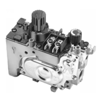
VS8421 VENTFREE MILLIVOLT GAS VALVE
5 69-1219—1
Lighting Pilot with Piezo
1. Turn the knob counterclockwise to the
PILOT position, push the knob down, and hold in
position. The pilot valve opens and allows gas to
flow to the pilot burner.
2. Push the plunger on the piezo until the pilot burner
is lit. Hold down the knob until a strong flame is
present (approximately 60 seconds).
3. Release the knob. The shaft will move upward and
engage the safety valve lever that opens the safety
valve.
4. Turn the knob counterclockwise to the ON
position. On a call-for-heat, the main valve opens
and the main burner ignites.
Shut off Procedure
1. To shut off the system, turn the knob
clockwise to the OFF position. This action
closes the main gas and safety valves; however,
the power unit must drop out before the lighting
sequence can begin again. The VS8421 drops out
within 30 seconds.
2. To relight the pilot light, follow the steps in the
Pilot Gas and Lighting Procedure section.
HI/LO Regulator
As you turn the HI/LO knob, the gas pressure changes.
1. Turn the knob clockwise toward the HI
setting to increase gas pressure.
2. Turn the knob counterclockwise toward
the LO setting to decrease gas pressure.
Minimum and maximum regulator settings vary for each
individual gas valve. Table 1 lists possible minimums and
maximums for gas valves. See gas valve label for actual
minimum and maximum ranges.
Table 1. HI/LO and Standard Regulator Pressures in in. wc (kPa).s
Standard Pressure Regulator
1. Check the manifold pressure listed on the
appliance nameplate. Gas valve outlet pressure
should match the nameplate.
2. With the main burner operating, check the gas
valve flow rate using the meter clocking method or
measure the pressure by attaching a plastic tube
with a 1/4 in. shell ID to the manometer and
connecting the manometer to the outlet pressure
tap on the gas valve. See Fig. 4.
3. If necessary, adjust the pressure regulator to
match the appliance rating. See Table 1 for
factory-set nominal outlet pressure and adjustment
range.
a. Remove the pressure regulator adjustment cap
screw.
b. Using a screwdriver, turn the inner adjustment
screw clockwise to increase or
counterclockwise to decrease gas
pressure to the burner.
c. Always replace the cap screw and tighten
firmly to prevent gas leakage.
4. If desired outlet pressure or flow rate cannot be
achieved by adjusting the gas valve, check the gas
valve inlet pressure using a manometer at the gas
valve inlet pressure tap. If inlet pressure is in the
normal range (see Table 1), replace the gas valve;
otherwise, take the necessary steps to provide
proper gas pressure on the valve.
CHECKOUT
Fire or Explosion Hazard.
Can cause property damage, severe injury or
death.
Do not force the gas control knob on the
appliance. Use only your hand to turn the gas
control knob. If the knob does not operate by
hand, the valve should be replaced by a qualified
service technician.
Gas Control Knob Settings
Gas control knob settings are as follows:
OFF: Prevents main gas flow through the valve.
ON: Permits main burner and pilot gas flow. Gas valve
and thermostat control main burner gas flow.
PILOT: Opens pilot valve and allows gas flow to the
pilot burner.
HI/LO: Manually adjusts outlet pressure.
NOTE: Valves are shipped with the gas control knob in
the ON position.
Type of Gas
HI/LO Regulator Setting Ranges
Standard Regulator Setting RangesHi Lo
natural 3.0 to 3.7 1.2 to 2.5 3.0 to 5.0
LP 9.0 to 12.0 3.5 to 6.5 8.0 to 12
69-1219-1.fm Page 5 Thursday, August 18, 2011 7:32 AM