WEB-700 WEB-700-O CP-700
95-7776—01 16
WEB-700; WEB-700-O; CP-700
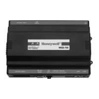
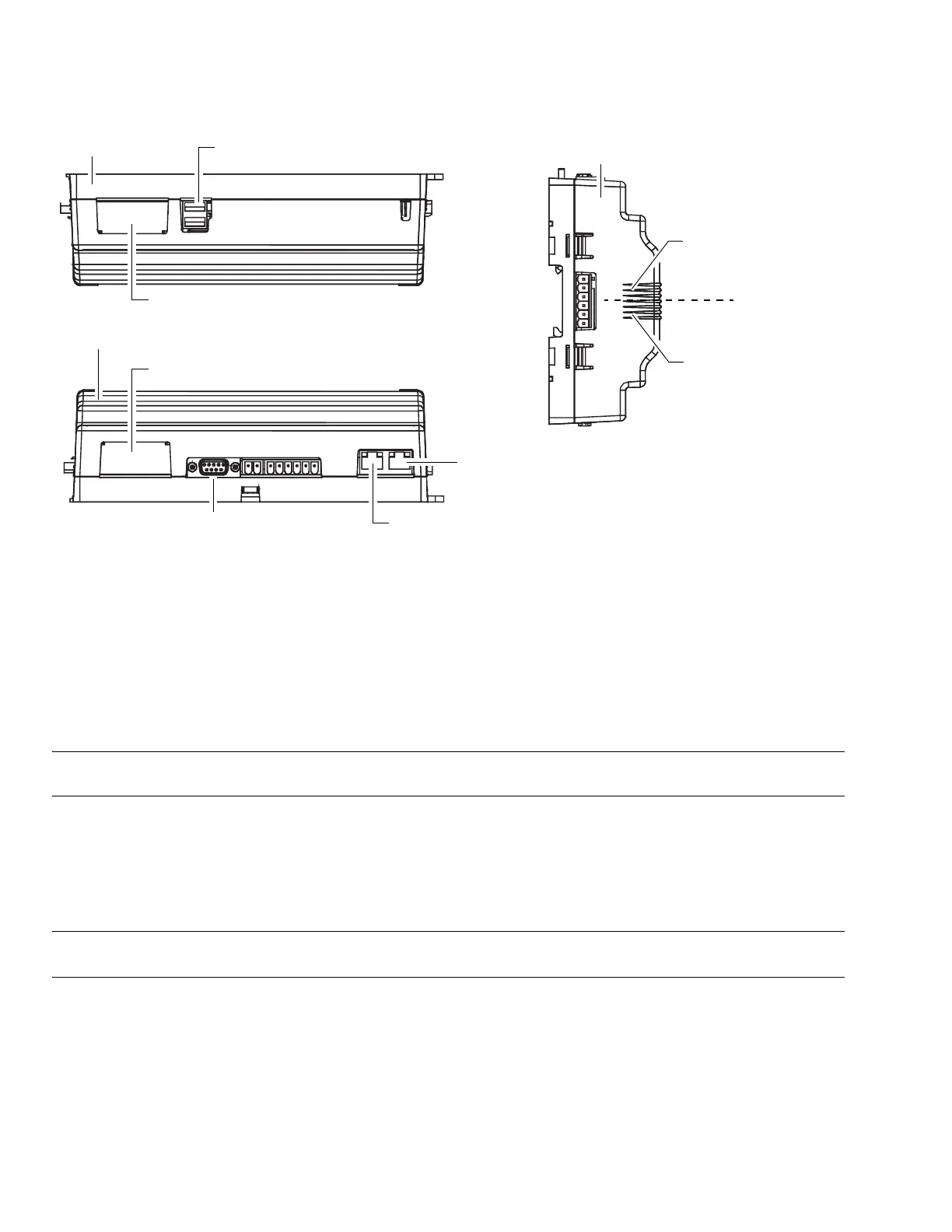
Fig. 7. WEB/CP-700 communications ports.
ETHERNET
Two, female 1-Gigabit Ethernet connections are provided on the WEB/CP-700. These are RJ-45 connectors labeled LAN1 and
LAN2. Use a standard Ethernet patch cable for connecting to a hub or Ethernet switch.
The factory-default IP address for LAN1 on a WEB/CP-700 is 192.168.1.14n, where the last numeral n in the address matches
the last digit in the WEB/CP-700’s serial number, and the subnet mask is 255.255.255.0. By default, LAN2 on a WEB/CP-700 is
disabled.
Refer to the NiagaraAX Install and Startup Guide for details on changing IP address.
NOTE: Typically, you only use LAN1 (primary port), unless you have a specific application for the other LAN2 port. For exam-
ple, isolating a driver’s network traffic, using LAN2. Do not use LAN2 as the primary port.
SERIAL
There are two “RS” serial ports on the WEB/CP-700 base board. Each has a UART capable of operation up to 115,200 baud. At
the bottom of the board (see Fig. 7, page 16) is an RS-232 port using an DB-9 plug (male) connector. On the right side of the unit
is an isolated RS-485 port, using the bottom three terminals of a 6-position screw-terminal connector plug.
NOTE: Additional serial ports may be added with option card(s) in Option Slot 1 and Slot 2, such as an NPB-RS232 card, or
NPB-2X-RS485 card (note the last option actually adds two serial ports).
In addition, there are two USB ports—these ports are located on the top side.
RS-232
An RS-232 serial port using a male DB-9 connector always operates as COM1. You can use standard DB-9 serial cables with this
port. The WEB/CP-700 is a serial DTE device, another DTE device (PC, for example) requires a “null modem” cable. If
connecting to a DCE device (modem, for example), use a straight-through cable. Table 4. provides standard serial DB-9 pinouts.
Option slot 2 connector area
Option slot 1 connector area
RS-232 (DB-9) COM1
USB ports (2)
RS-485 COM2
15V PS -, + and
12V Backup Battery out
Bottom side
Right side
Top side
LAN 2 Ethernet (RJ-45)
LAN 1 Primary Ethernet (RJ-45)
 Loading...