WEB-700 WEB-700-O CP-700
9 95-7776—01
WEB-700; WEB-700-O; CP-700
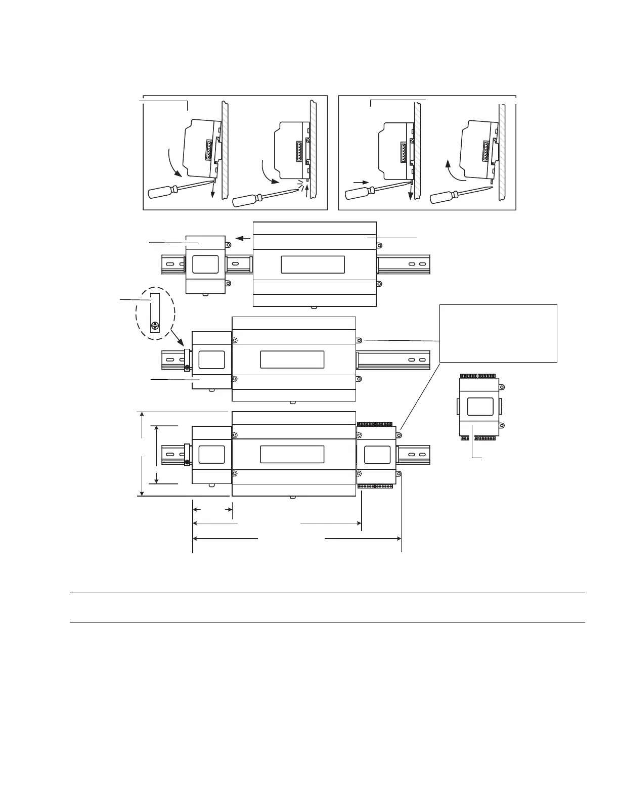
Fig. 3 and the following procedure provides step-by-step DIN rail mounting instructions for the WEB/CP-700.
Fig. 3. WEB/CP-700 and accessory mounting details.
NOTE: Mount the NPB-PWR-UN-H power supply first, then the WEB/CP-700 controller, then any directly attached I/O expan-
sion module.
To mount on DIN rail
1. Securely install the DIN rail with at least two screws, near the two rail ends.
2. Position the NPB-PWR-UN-H power supply module on the rail, tilting to hook DIN rail tabs over one edge of the DIN rail
(Fig. 3).
3. Use a screwdriver to pry down the plastic locking clip, and push down and in on the module, to force the locking clip to snap
over the other edge of the DIN rail.
4. Mount the WEB/CP-700 controller onto the DIN rail in the same way, such that its left 6-position end connector faces the
NPB-PWR-UN-H power supply.
5. Slide the two devices together along the DIN rail to connect their 6-position connectors.
4.1" (104)
5.6"
(142)
3.46"
(88)
11.75" (298)
15.125" (384)
Mounting on
DIN rail
Removing from DIN rail
NPB-PWR-UN-H
DIN rail
end clip
NPB-PWR-UN-H
IO-16-REM-H
WEB/CP-700
Secure controller or last
directly attached I/O module
using either screws or DIN
rail end clip (if end clip does
not interfere with 6-position
end connector).
 Loading...