WEB/CP-202-XPR AND WEB/CP-602-XPR CONTROLLERS
95-7775—01 16
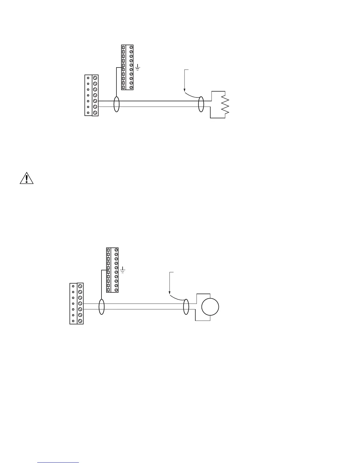
Fig. 9. Thermistor sensor wiring diagram.
Resistive 0 to 100K ohms
Inputs can read a resistive signal within a range from 0 to 100,000 ohms. Wiring is the same as shown for a Thermistor
temperature sensor (Fig. 9.). Resistive signals require a ResistiveInputPoint.
UI inputs provide optimum resistive-to-temperature resolution in the 10K ohm range. For a sensor with a range
far from 10K ohms (such as a 100-ohm or 1000-ohm sensor), resolution is so poor as to be unusable! To
successfully use such a sensor, install a transmitter that produces a Vdc or mA signal, and then wire the
transmitter to the UI according to the 0 to 10 Vdc or 4 to 20 mA instructions.
0 to 10 Vdc
Inputs support self-powered 0 to 10 Vdc sensors. Input impedance is greater than 5K ohms. 0 to 10 volt accuracy is ±2% of span,
without user calibration. Fig. 10. shows the wiring diagram for a 0 to 10 Vdc sensor.
Fig. 10. 0 to 10 Vdc sensor wiring diagram.
4 to 20 mA
Inputs support self-powered or controller-powered 4 to 20 mA sensors. The input requires an external 499 ohm resistor for
current input (four resistors are supplied). For controller-powered sensors, the controller’s two V+ terminals supply 24 Vdc, at up
to 80 mA combined. Input accuracy is ±2% of span, without user calibration.
Fig. 11 on page 17 shows wiring used for a self-powered sensor (top) and a 2-wire controller-powered sensor (bottom).
M28871
SHIELDED, TWISTED CABLE,
200 FEET (61 M) MAXIMUM
CUT AND TAPE
SHIELD WIRE
BACK AT THERMISTOR
SHIELD
USE POINT: ThermistorInputPoint
10K THERMISTOR
GND
V +
UI4
UI3
UI2
UI1
GND
M28872
SHIELDED, TWISTED CABLE,
200 FEET (61 M) MAXIMUM
CUT AND TAPE
SHIELD WIRE
BACK AT SENSOR
SHIELD
USE POINT: VoltageInputPoint
CONVERSION: Linear
0 TO 10 VDC SENSOR
(SELF POWERED SENSOR)
RANGE: 0 TO 10 VDC
INPUT IMPEDANCE: > 5K OHMS
GND
V +
UI4
UI3
UI2
UI1
GND
+
–
0 TO 10
VDC

 Loading...