WEB/CP-202-XPR AND WEB/CP-602-XPR CONTROLLERS
17 95-7775—01
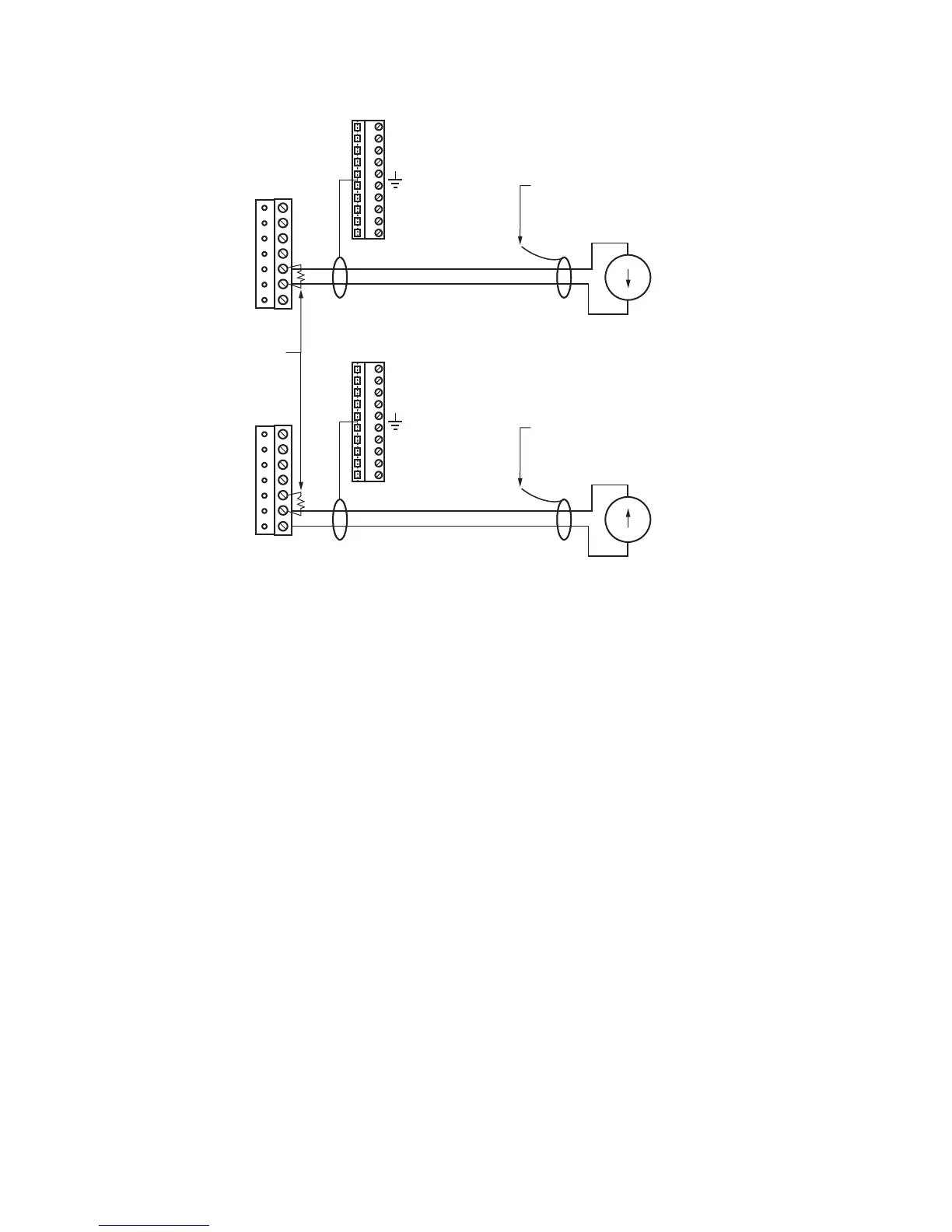
Fig. 11. 4 to 20 mA sensor wiring diagram.
A 4 to 20 mA sensor requires a VoltageInputPoint, using conversion type 500 Ohm Shunt, and secondary conversion type
Linear.
Binary Input
Inputs support both pulse contacts and normal dry (equipment status) contacts.
• Pulse contacts may have a change-of-state (COS) frequency of up to 20 Hz with a 50% duty cycle.
Note: Minimum dwell time must be > 25ms.
(Contacts must remain open at least 25ms and be closed at least 25ms.)
• Standard dry contacts must have a 1 Hz. (or less) COS frequency, with minimum dwell time > 500ms.
(Contacts must remain open at least 500ms and be closed at least 500ms.)
Both types of dry contacts support 3.3 Vdc open circuits or 330 µA short-circuit current.
Fig. 12 on page 18 shows the wiring diagram. For a pulse contact, use the CounterInputPoint in the station database.
For other dry contacts, use the BooleanInputPoint.
M28873
SHIELDED, TWISTED CABLE,
200 FEET (61 M) MAXIMUM
CUT AND TAPE
SHIELD WIRE
BACK AT SENSOR
SHIELD
USE POINT: VoltageInputPoint
CONVERSION: 500 Ohm Shunt
SECONDARY CONVERSION: LINEA
4 TO 20 mA SENSOR
(SELF POWERED)
RANGE: 4 TO 20 mA
GND
V +
UI4
UI3
UI2
UI1
GND
+
–
SHIELDED, TWISTED CABLE,
200 FEET (61 M) MAXIMUM
CUT AND TAPE
SHIELD WIRE
BACK AT SENSOR
SHIELD
4 TO 20 mA SENSOR
(CONTROLLER POWERED)
RANGE: 4 TO 20 mA
GND
V +
UI4
UI3
UI2
UI1
GND
+
–
499 OHM RESISTOR
(SUPPLIED WITH UNIT)
i
i

 Loading...