EasyManua.ls Logo

Honeywell WV8840B User Manual

Honeywell WV8840B
8 pages
To Next Page IconTo Next Page
Page #1 background imageLoading...
Page #1 background image
INSTALLATION INSTRUCTIONS
69-2450-03
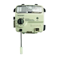
WV8840B Water Heater Controls
APPLICATION
The WV8840 Water Heater Control is designed for use in
Standing Pilot applications using an immersion well for
water temperature sensing. All models of WV8840
include an integrated NTC temperature sensor.
The WV8840 is powered from a thermopile heated by the
standing pilot flame. CS8840 pilot assemblies are
designed for use with this control.
The immersion well for sensing water temperature has
matched NTC thermistor sensors. These sensors
provide the fail-safe mechanism through which the
WV8840 can provide both accurate water temperature
control as well as water temperature limit (Temperature
Cut-Out [TCO]) function.
SPECIFICATIONS
IMPORTANT
WV8840 controls provide direct replacement
only.
Pressure Regulator: The outlet pressure regulator
setting is shown on the product label.
Inlet Pressure Range:
See appliance rating plate for inlet pressure range
recommendation.
1/2 PSI (14.0 in. w.c.) maximum inlet pressure allowed
for proper operation.
Body Pattern: 90 degrees with 1/2 in. inlet and 1/2 in.
inverted flare outlet.
Mounting: Mounting in upright position only.
Control Input:
Voltage Minimum: 350 mV dc, open circuit.
Voltage Maximum: 850 mV dc, open circuit.
Capacity: See Table 1.
Regulation Range:
Natural Gas:
Minimum: 30,000 Btuh.
Maximum: 85,000 Btuh.
Ambient Temperature Range: 32°F to 150°F
(0°C to 66°C)
Operating Range: 0°F to 150°F (-18°C to 66°C)*
Storage Range: -40°F to 150°F (-40°C to 66°C)
* Valve will operate at 0°F (-18°C) but valve characteris-
tics can not be guaranteed until ambient temperature
reaches 32°F (0°C).
Humidity: 95% non-condensing at 104°F (40°C)
Approvals:
This device is certified by Canadian Standards Associa-
tion (CSA) to the following standards:
ANSI Z21.20
ANSI Z21.23
ANSI Z21.78
ANSI Z21.87
CAN/CSA-C22.2 No. 199-M89
CAN1-6.6-M78
CSA 4.6
CSA 6.20
Accessory Parts:
Pilot Assembly CS8840

Questions and Answers:

Honeywell WV8840B Specifications

General IconGeneral
ModelWV8840B
ManufacturerHoneywell
CategoryControl Unit
Voltage24 VAC
TypeGas Control
Gas TypeNatural Gas or Propane
Operating Temperature-40°F to +175°F (-40°C to +79°C)
Humidity Range5 to 95% RH
Communication ProtocolModbus

Summary

APPLICATION

Operating Conditions

Covers temperature and humidity ranges for operation and storage.

Approvals and Accessories

Lists device certifications and available accessory parts.

SPECIFICATIONS

Key Specifications

Includes pressure, mounting, and input voltage requirements.

Direct Replacement Note

Highlights that WV8840 controls are for direct replacement only.

PLANNING THE INSTALLATION

Installation Considerations

Covers frequent cycling, water/steam, humidity, chemicals, dust, and heat.

Flow Capacity & Pressure Drop

Capacity Curve and Data

Presents the typical capacity curve and gas capacity conversion table.

INSTALLATION

Installation Prerequisites

Lists essential steps and warnings before commencing installation.

Location

Mounting Diagram

Illustrates how to mount the WV8840 control on the water heater tank.

Install Control to Water Tank

Installation Note

Advises not to remove protective caps until ready to connect piping.

Connect Gas Supply

Safety and Sediment Trap

Warns about explosion hazards and shows sediment trap installation.

Wiring

Wiring Compliance

Emphasizes that all wiring must comply with applicable electrical codes.

Fill Tank

Manufacturer Instructions

Directs users to appliance manufacturer instructions for filling the tank.

Pilot Gas and Lighting Procedure

Lighting Notes

Explains purge time for air and LED blinking patterns for normal operation.

Turn on Main Burner

Scalding Hazard Warning

Warns about scalding hazards and proper temperature adjustment.

Perform Gas Leak Test

Safety and Leak Test Procedure

Covers safety warnings, water damage caution, and leak test steps.

Check Gas Input and Burner Flow Rate

Safety and Input Checks

Includes safety warnings and procedures for checking gas input via meter or manometer.

MAINTENANCE AND TROUBLESHOOTING

Maintenance Guidance

Discusses maintenance frequency, criteria, and safety warnings.

Troubleshooting with Status Indicator

Describes how to use the status indicator for diagnosing issues.

Troubleshooting With Status Light Visual Indication

LED Error Codes and Actions

Lists LED error codes, detected failures, and recommended actions.

Troubleshooting Without Status Indicator Assistance

Troubleshooting Flowchart

Provides a flowchart for troubleshooting when the status light is not available.

Thermopile Output Check

Thermopile Output Graph

Shows a graph of thermopile output over time for diagnosis.

INSTRUCTIONS TO THE HOMEOWNER

Homeowner Safety Warnings

Provides critical safety instructions for homeowners regarding gas smell and scalding.

TURNING OFF THE APPLIANCE

Complete Shutdown Procedure

Details the steps for completely shutting down the appliance.

Related product manuals