XNX Universal Transmitter
Installation and Operation
60
Modbus connections to the transmitter are made through
a pluggable terminal block on the Modbus interface circuit
board. Modbus RTU protocol uses ASCII/Hex protocols for
communication. See the Terminal block legend for the terminal
block legend. A loop termination point (SW5) is included on the
Modbus interface board to provide termination of the Modbus
loop.
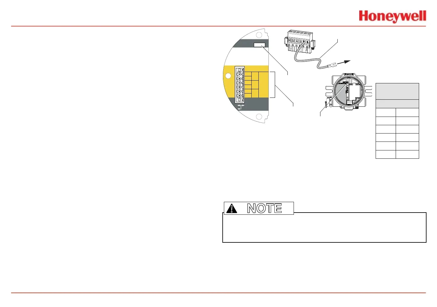
FOUNDATION Fieldbus
FOUNDATION Fieldbus connections to the transmitter are
made through a pluggable terminal block on the FOUNDATION
Fieldbus option board, shown in the gure below. A simulation
switch (SW5) is included on the board to enable/disable
simulation mode. Terminals 3-1 through 3-4 are provided to
facilitate bus wiring; there is no internal connection to other XNX
circuitry. Terminal 3-1 is connected internally to 3-2. Similarly,
terminal 3-3 is connected internally to 3-4.
+
+
TB-3 Modbus
Use shorting jumper
supplied to maintain
connection during
service
S5 Sim Mode
Out
In
3-1
3-2
3-3
3-4
3-5
3-6
F+
F+
F-
F-
FS
FS
TB-3 FFB
Jumper
assignments
1
2
3
4
5
6
to internal
ground lug
SW5 -
Sim switch
Internal ground lug
FOUNDATION Fieldbus
ground cable
FOUNDATION
Fieldbus
TB3
1 F+
2 F+
3 F-
4 F-
5 FS
6 FS
Figure 59. FOUNDATION Fieldbus option board, terminal block, jumper switch
Note: FOUNDATION Fieldbus XNX transmitters require a separate power source and
cannot be powered via the bus.
!

 Loading...

