16
2-way RF devices that communicate with each other achieve this through having each others unique addresses written in their memories. This allows
each device to know which other device to communicate with. The process of writing these addresses is known as Binding.
All devices in the pack are pre-bound at the factory. The binding operation is only required if:
- any of the system components are replaced
- pre-bound system pack components have been mismatched
- additional components are required for the application, e.g. BDR91T relay box for remote boiler application 95-3. In this case the
BDR91T must be bound to the ST9520C as a BOILER CONTROL (see section 6.6).
The ST9520C is the communications ‘hub’ of the entire system, so other RF devices are bound to it and not to each other. ST9520C has a special
‘Guided Binding Menu’ that allows you to bind other devices to it in a logical way. Devices are bound into special ‘slots’ and there are rules governing
what can be bound into which slot. This ensures binding errors are minimised and applications are correctly set up. When in ‘Guided Binding Menu’
the and buttons are used to navigate around.
Sensor binding (refer to section 6.5 for sequence of steps)
It is possible to bind 2 sensors to ST9520C in separate binding slots, a DT92E thermostat for Zone 1 and a DT92E thermostat for Zone 2. If the display
shows dashes it means there is nothing already bound in the slot. If the display shows ‘bnd’ it means there is something already bound.
Control and boiler binding (refer to section 6.6 for sequence of steps)
Once a valid sensor is bound, it is then possible to bind an output device, such as a BDR91T relay box. If this is to control remote zone valves for the
heating zones, then use the CONTROL binding slots. In the special case of controlling a remote boiler, use the special BOILER binding slot. When
this is bound, the Guided Binding Menu then allows a signal strength test to be initiated (refer to section 6.7 for sequence of steps).
Binding table by application
General Binding Notes
• Tobind2devicestogether,BOTHmustbeputintoBindingMode.
• Withbothdevicesinbindingmode,youmustsendthebindingsignalfromonedevicetotheother:
- To bind a sensor, the signal is sent from the sensor.
- To bind an output device, the signal is sent from the ST9520C.
6
BINDING / RE-BINDING PROCEDURE
6.1 Binding
6.2 ST9520C Guided Binding Menu
6.3 Guidance for Replacing Devices or Changing the Application
Situation Binding Action
1. Replacing faulty DT92E • BindnewsensoroverpreviousbindinginSENSORslot.
2. Replacing faulty BDR91T • BindnewBDR91ToverpreviousBDR91TinCONTROLorBOILERslotand
remove faulty BDR91T from system.
3. Reconfiguring system by adding or removing BDR91T • IfremovingBDR91T,cancelbindinginthatCONTROLorBOILERslot.
• IfaddingBDR91T,bindintovacantCONTROLorBOILERslot.
Note: if a sensor is removed, the binding for any output device associated with that sensor will be cancelled.
Application Zone 1 Sensor Zone 2 Sensor Zone 1 Control
Output
Zone 2 Control
Output
Boiler
Output
Binding Required
SENSOR SENSOR CONTROL CONTROL BOILER
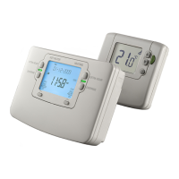
95-1 DT92E DT92E -- -- -- -- -- -- Supplied pre-bound
95-2 DT92E DT92E -- -- -- -- -- -- Supplied pre-bound
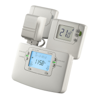
95-3 DT92E DT92E -- -- -- -- BDR91T Bind in BDR91T
 Loading...