Instructions for Use
ComPass B 4023841-001
LED Meaning
green
ComPass B is powered from external supply (permanent light)•
No error (permanent light)•
yellow
Test mode (single ashing LED) and device error (double ashing LED; •
contact after-sales service)
red
Fault in the MV system (LED ashes)•
No indication, external supply not connected.•
No error present.•
Indication of operating conditions by multicolour LEDTable 1:
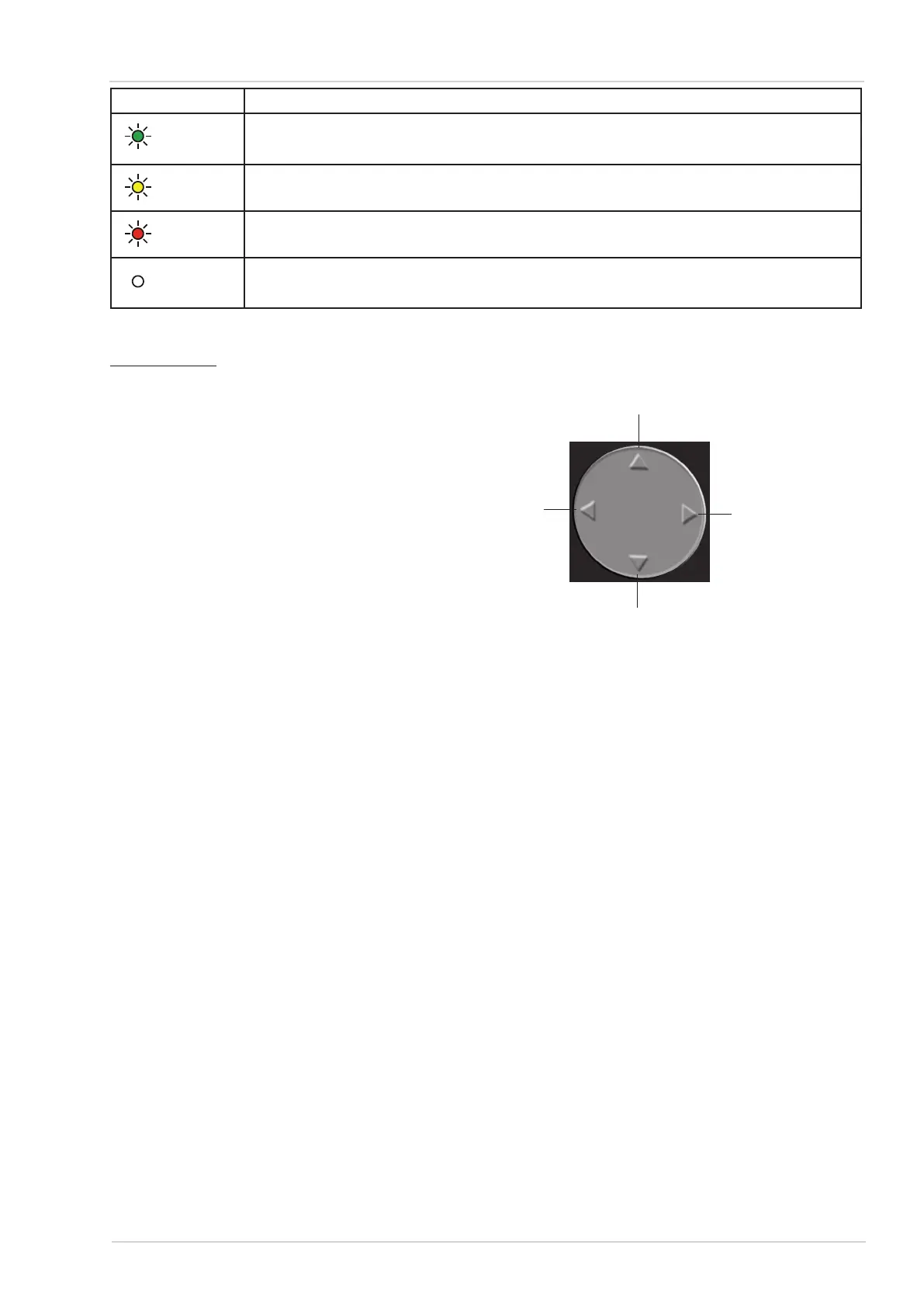
Rocker switch
The rocker switch is used for navigating the plain text menus on the display.
Up: Scroll up in a menu. 1.
Change (increase) a parameter.
Down: Scroll down in a menu. 2.
Change (reduce) a parameter.
Left: Leave menu (abort). 3.
Jump to main menu.
Right: Call submenu. 4.
Save a changed parameter.
1.
4.
3.
2.
Execute a command.
Rocker switch Figure 17:
RS485/MODBUS interface3.3.2.
The RS485/MODBUS interface is used for remote control, remote readout and remote parameteri-
zing of ComPass B.
The ComPass B uses a 2-wire interface according to the RS485 standard with no line termination
in the ComPass B.
The ComPass B is a MODBUS Remote Terminal Unit (RTU) Slave.
Digital inputs/outputs3.3.3.
The ComPass B is provided with 4 digital (relay) outputs and one digital input. Each relay output
can be assigned with individual functionality either via the front panel control or the RS485/MOD-
BUS interface.
Power Supply3.4.
The ComPass B is powered by an external 24-230 V AC/DC ±10 % supply. An incorporated lithium
cell provides the energy in case of lack of external voltage supply, so the readout of all saved data
is ensured in case of a fault.
If external power supply stops, the ComPass B will stop short-circuit and earth fault detection as
well as MV network monitoring and communication via the RS485/MODBUS interface. It is ensured
that the relays are energized, even in case of a fault.
11
Dipl.-Ing. H. Horstmann GmbH