Instructions for Use
ComPass B 4023841-001
The ComPass B works with the following response criteria:
Overcurrent detection for phase currents (I>>) and earth current (I•
E
>)
Earth current and neutral point displacement voltage (I•
E
> & V
NE
>) for resonant earthed/isolated
networks
Overvoltage (V>) and undervoltage (V<)•
The unit allows individual settings of delay times for all of the above mentioned response criteria.
Whenever one or more of the specied response criteria are met, the ComPass B identies the na-
ture of the error and determines the direction of the fault using the sampled values of the affected
voltages and currents.
Fault direction3.1.2.
Short-circuit/earth fault in solidly earthed & low-impedance systems
As for short-circuits and earth fault in solidly earthed and low-impedance systems, the ComPass B
determines the angle between the fault current and the fault voltage of the affected phases to de-
rive the direction of a fault therefrom. If the impedance angle ranges from -45° to +135°, the Com-
Pass B determines a forward fault (↓B direction).
Earth fault in resonant earthed/isolated systems
As for earth faults in resonant earthed/isolated networks, the ComPass B uses the wattmetric me-
thod. Here the direction of a fault is determined by the phase-to-neutral voltage V
NE
and the earth
fault current I
E
.
In some cases it is not possible to determine the direction of a fault, especially when the fault is
located close to the switchgear unit the ComPass B is installed into. In such cases the ComPass B
signals an error without directional indication.
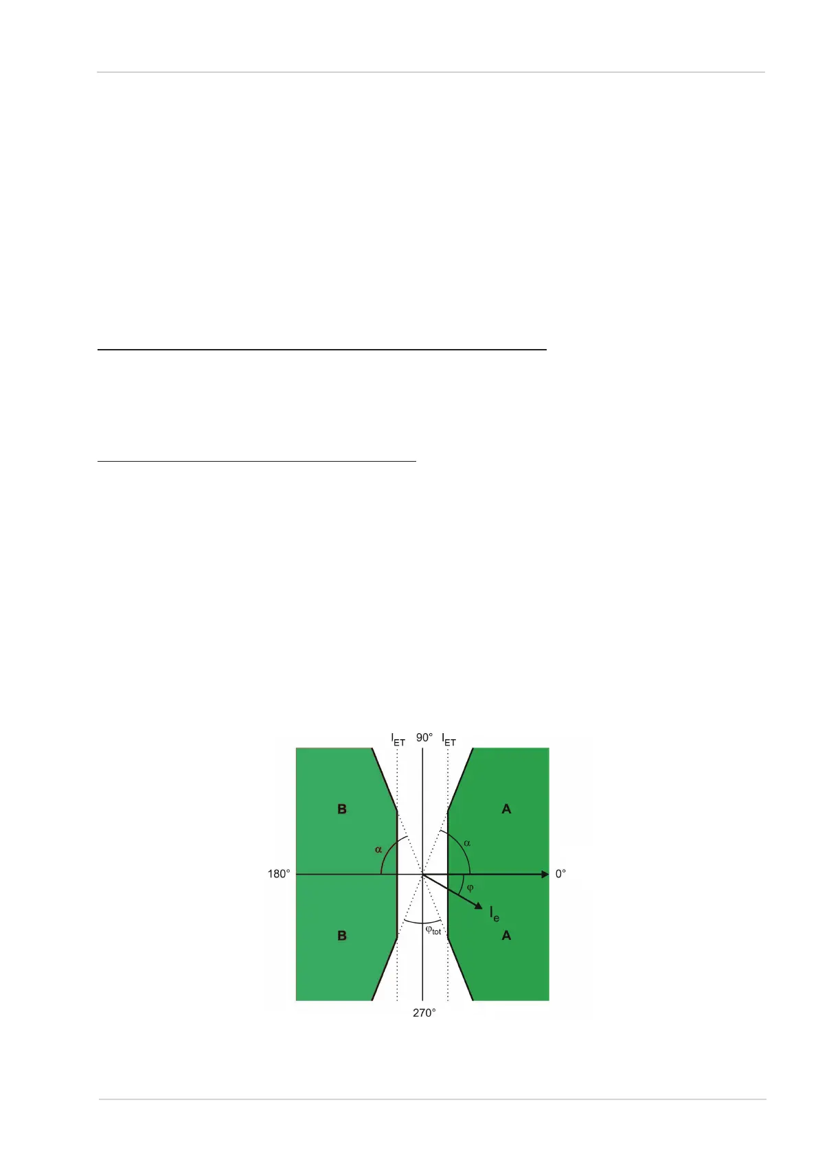
Resonant earthed network operation (cos φ) •
In resonant earthed networks, the ComPass B determines the direction of the active power
of the earth fault (V
NE
x I
E
x cos φ)
The ComPass B is provided with an integrated dead zone (non-coloured area, see gure
10) for too low levels of earth fault current I
E
, or for phase angles that are unfavourably loca-
ted between V
NE
and I
E
.
Angle diagramFigure 10:
V
NE
7
Dipl.-Ing. H. Horstmann GmbH