Instructions for Use
ComPass B 4023841-001
G
Important note for the connection of the external input (see Table 2)
For activation of the functions use potential-free contacts, e. g. coupling relays or tra-•
cers.
Use separate potential-free contacts for each indication device.•
If the functions of several devices shall be operated in parallel, the triggering disconnec-•
ting elements (relay outputs, coupling relays etc.) are to be operated in parallel.
Operational earth or other "GND" potentials are inappropriate as common reference po-•
tential.
Use a momentary contact for triggering (momentary time 1-5s), but not a permanent •
contact.
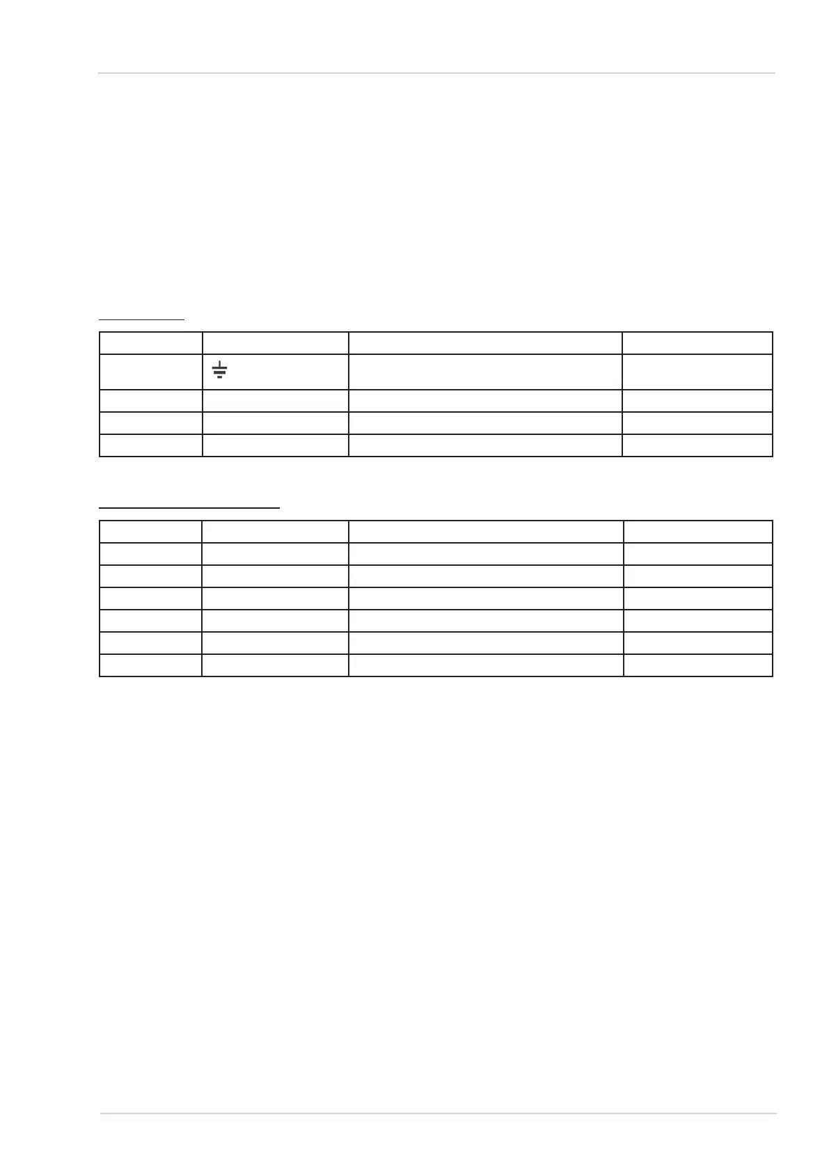
MV interface
Terminal No. Designation Assignment Direction
1
Earth Input/Output
2 U1 Voltage/Phase 1 Input
3 U2 Voltage/Phase 2 Input
4 U3 Voltage/Phase 3 Input
Terminal assignment of MV interfaceTable 3:
RS485/MODBUS interface
Terminal No. Designation Assignment Direction
1 COM Common Input/Output
2 RES Reserved Reserve
3 RES Reserved Reserve
4 RES Reserved Reserve
5 B D1/RS485 "B" Input
6 A D0/RS485 "A" Input
Terminal assignment of RS485/MODBUS interfaceTable 4:
Device conguration and commissioning5.
Device configuration5.1.
ComPass B is delivered with a standard factory setting (see Appendix A) which, in most cases,
meets all requirements. Some parameters (see Table 5) however need to be set and checked indi-
vidually which can be carried out either via the front panel control or the RS485/MODBUS interface.
G
Any alteration in the conguration should be carried out while assuring that the ComPass B is
supplied by an external supply, otherwise parameter storage may fail.
15
Dipl.-Ing. H. Horstmann GmbH