Instructions for Use
ComPass B 4023841-001
Electrical connection4.4.
Terminal strips4.4.1.
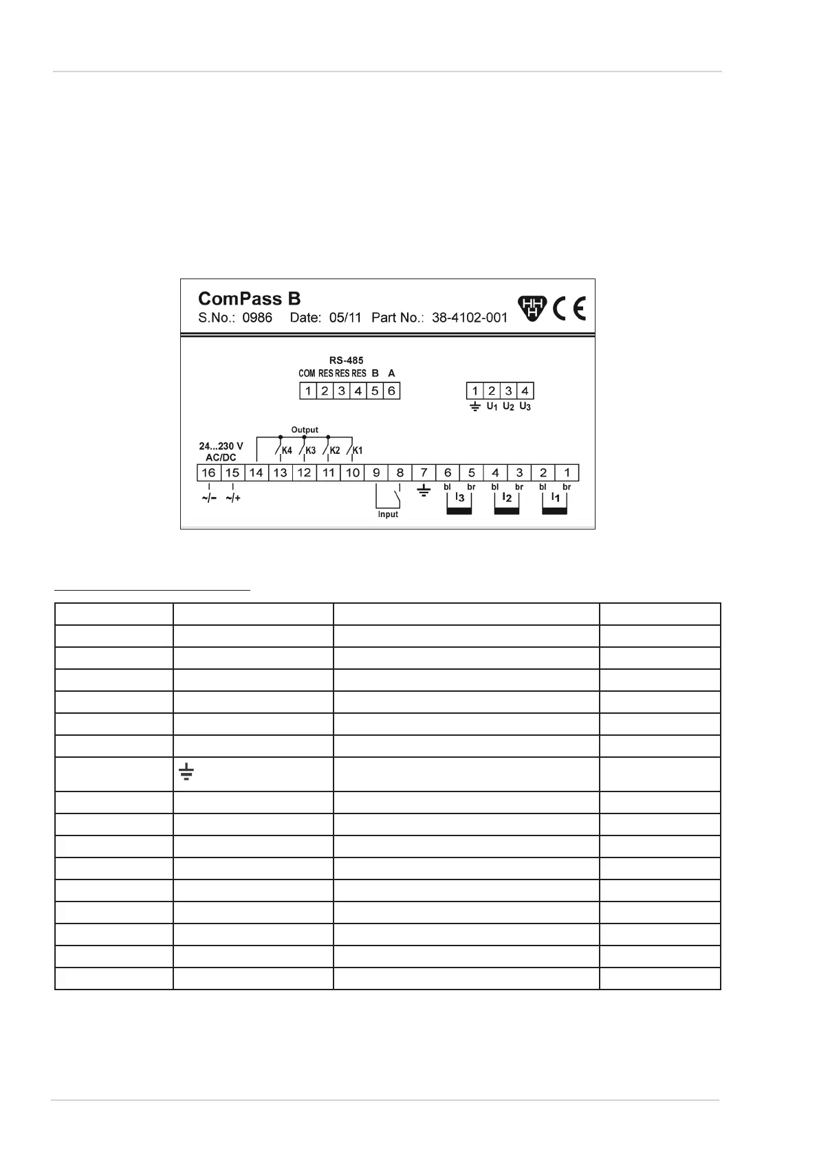
The terminal strips are located in the rear wall of the instrument. If provided on the side of the
switchgear, perform electrical connection according to the following terminal reference list (See also
circuit diagram on the top side of the instrument, numerical arrangement from right to left). Use fer-
rules of L=6 mm, max. 0.75 mm2 .The maximum permissible tightening torque is 0.4 Nm.
Assignment of terminal strips4.4.2.
Circuit diagram on top side of the instrumentFigure 20:
CT/Digital I/O/Supply Voltage
Terminal No Designation Assignment Direction
1 I1 br CT Phase 1 (brown) Input
2 I1 bl CT Phase 1 (blue) Input
3 I2 br CT Phase 2 (brown) Input
4 I2 bl CT Phase 2 (blue) Input
5 I3 br CT Phase 3 (brown) Input
6 I3 bl CT Phase 3 (blue) Input
7
Earth Input/Output
8 Input External input Input
9 Input External input Input
10 K1 Relay 1 Output
11 K2 Relay 2 Output
12 K3 Relay 3 Output
13 K4 Relay 4 Output
14 | Common contact for all relays Output
15 24-230 V ~/+ 24-230 V AC/DC ~/+ Input
16 24-230 V ~/- 24-230 V AC/DC ~/- Input
Terminal assignment of CT/Digital I/O/Supply VoltageTable 2:
14
Dipl.-Ing. H. Horstmann GmbH