36
J Front Panel
1. Remove the table top (A), dispenser drawer (C) and console panel (D).
2. Remove the door seal restraint (G) and door interlock (H).
3. Grip the appliance kickstrip at both ends tilt forwards, and pull it off in a forward direction.
4. Remove 4 front panel fixing screws (2 bottom and 2 top).
5. Slide the dispenser housing backwards so that it clears the console backplate opening.
6. Lift the front panel upwards to disengage the four cabinet fixing pegs, and lift off.
K Door Seal
1. Remove the table top (A), dispenser drawer (C) and console panel (D).
2. Remove the door seal restraint (G), door interlock (H) and front panel (J).
3. Remove the drum door seal restraint (G) and lift clear.
4. Disconnect from heater box nozzle.
L Drive Belt
1. Remove the table top (A).
2. Remove the lower rear access panel (B).
3. Carefully peel the belt off the motor pulley taking care not to trap fingers and using suitable
protection against sharp edges.
4. To refit the belt, place it round the motor pulley first, tie-wrap the belt onto the drum pulley, and
rotate the drum from the door aperture to move the belt into position.
5. Ensure any remaining tie-wraps are removed.
It is essential for continued safety that only a genuine spare is fitted. The belt is electrically
conductive and provides an electrical earth to prevent static built up on the inner drum assembly.
N(a) Lower Balance Weight
1. Remove the table top (A), dispenser drawer (C) and console panel (D).
2. Remove the door seal restraint (G), door interlock (H) and front panel (J).
3. Using a 13 mm socket or spanner, remove three balance weight fixing screws.
M Motor
1. Remove the lower rear access panel (B) and
drive belt (L).
2. Disconnect the motor wiring connection plug
and earth wire.
3. Using a 13 mm socket or ratchet ring spanner,
remove both motor mount fixing screws.
4. Ease the motor off the drum mountings.
5. Prior to refitting the motor, ensure that the drip
shield and mounting-bush are not worn or
damaged.
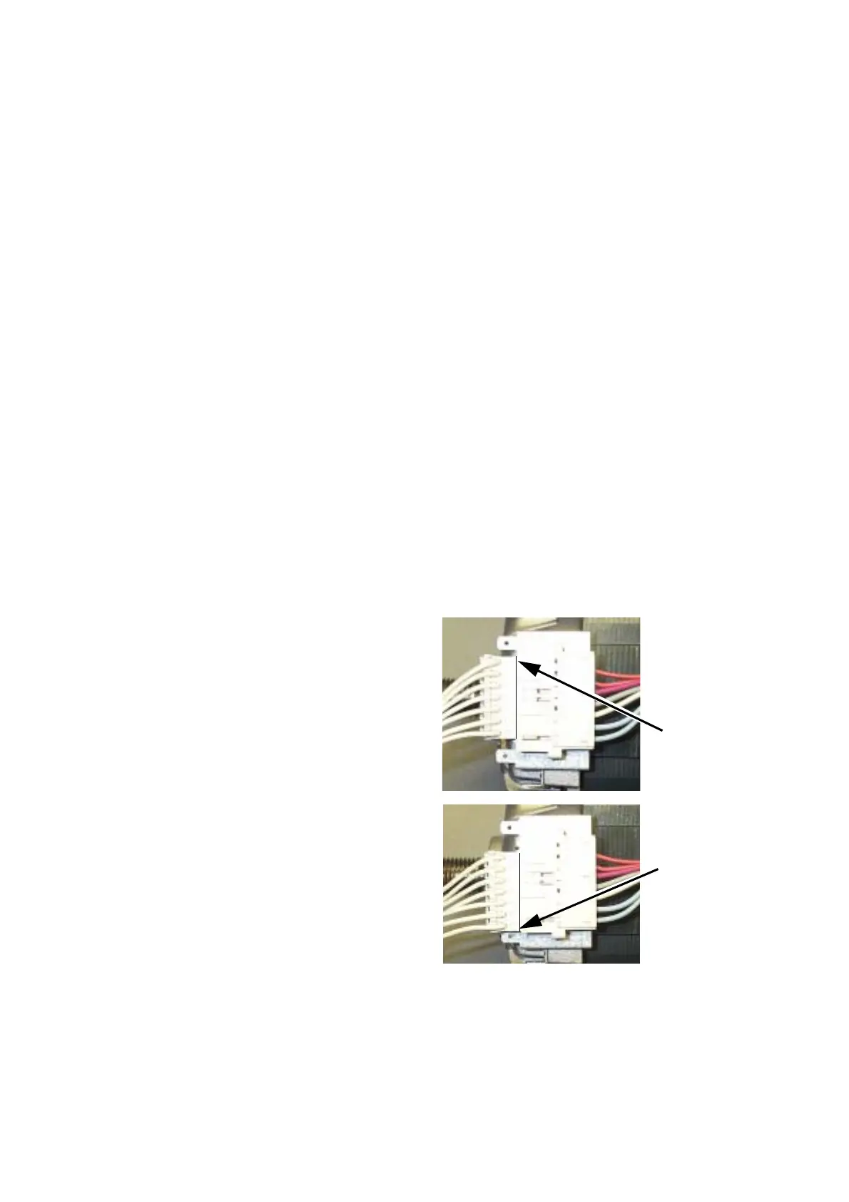
6. When refitting the motor plug, ensure correct
positioning of the motor plug as shown with all
cables aligned - see Fig. 7.
WRONG
CORRECT
Fig. 7
wiring colours shown
here may be different
on the appliance
 Loading...