33
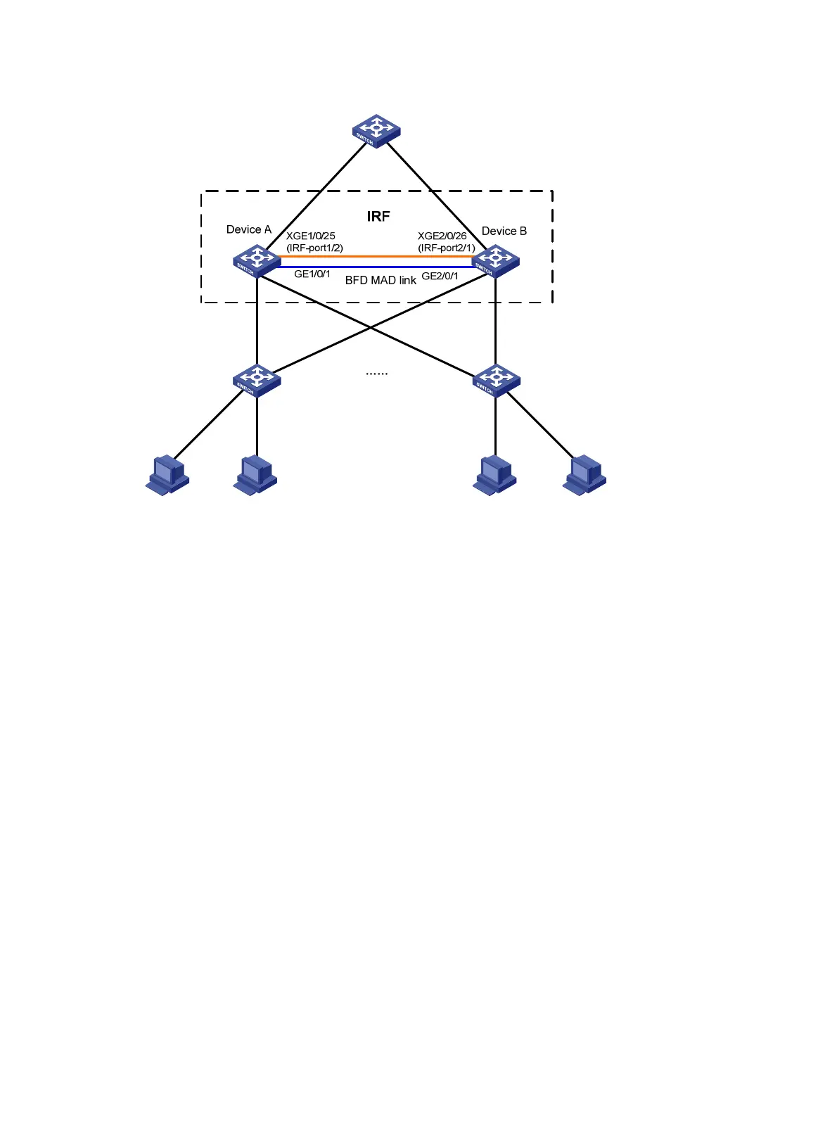
Figure 14 Network diagram
Configuration procedure
This example assumes that the system names of Device A and Device B are DeviceA and DeviceB
respectively before the IRF fabric is formed.
1. Assign member IDs:
# Keep the default member ID of Device A unchanged.
# Change the member ID of Device B to 2.
<DeviceB> system-view
[DeviceB] irf member 1 renumber 2
Warning: Renumbering the switch number may result in configuration change or loss.
Continue? [Y/N]:y
[DeviceB]
2. Power off the member devices, connect IRF links as shown in Figure 14, and power on the two
devices.
3. Configure IRF port bindings:
# Bind Ten-GigabitEthernet 1/0/25 to IRF-port 1/2 on Device A and save the configuration.
<DeviceA> system-view
[DeviceA] interface ten-gigabitethernet 1/0/25
[DeviceA-Ten-GigabitEthernet1/0/25] shutdown
[DeviceA-Ten-GigabitEthernet1/0/25] quit
[DeviceA] irf-port 1/2
[DeviceA-irf-port1/2] port group interface ten-gigabitethernet 1/0/25
[DeviceA-irf-port1/2] quit
[DeviceA] interface ten-gigabitethernet 1/0/25
[DeviceA-Ten-GigabitEthernet1/0/25] undo shutdown
[DeviceA-Ten-GigabitEthernet1/0/25] save
# Bind Ten-GigabitEthernet 2/0/26 to IRF-port 2/1 and save the configuration.
 Loading...