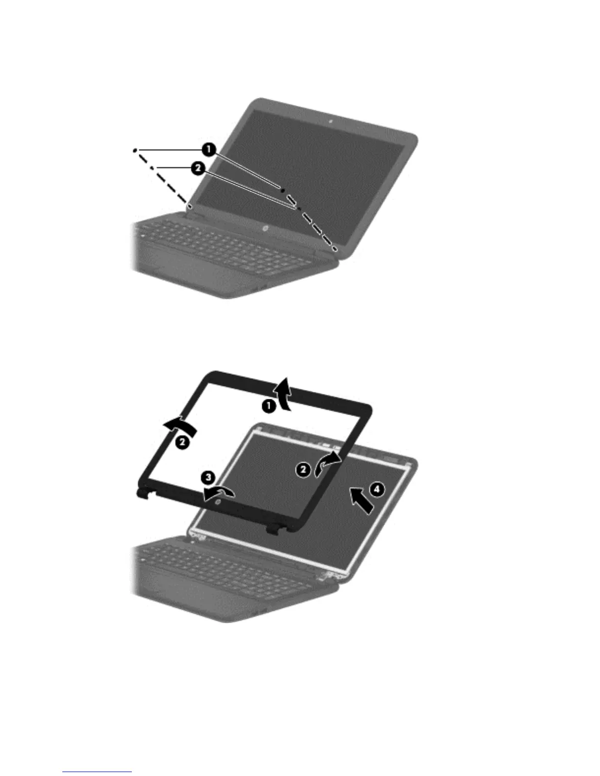
2. Remove the two Mylar screw covers (1) and the two Phillips PM2.5×4.5 screws (2) that secure the
display bezel to the display assembly.
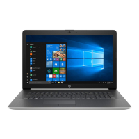
3. Flex the inside of the top edge (1), the left and right sides (2), and the bottom edge (3) of the display
bezel until the bezel disengages from the display enclosure.
4. Remove the display bezel (4).
5. To remove the webcam/microphone module:
a. Position the display assembly with the top edge toward you.
b. Disconnect the cable (1) from the module.
Component replacement procedures 45