Do you have a question about the HP 1620 Series and is the answer not in the manual?
Guidelines to avoid equipment damage or bodily injury during installation.
Requirements for the physical location where the switch will be installed.
Step-by-step instructions for rack mounting the switch using brackets.
How to connect a PC or network device using an Ethernet cable.
Initial steps to connect a console terminal to the switch.
Required settings for a terminal emulator to connect to the switch.
Common issues and their corresponding troubleshooting steps.
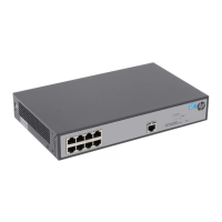
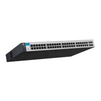
The HP 1620 Gigabit Ethernet Switch Series is a line of network switches designed for indoor use, offering reliable and efficient network connectivity. This Getting Started Guide provides comprehensive instructions for preparing the installation site, installing the switch, connecting necessary cables, accessing the switch for the first time, and basic troubleshooting. The series includes models such as the HP 1620-8G, HP 1620-24G, and HP 1620-48G switches, each identified by a unique product code and Regulatory Model Number (RMN).
The HP 1620 Gigabit Ethernet Switch Series serves as a central component in a local area network (LAN), facilitating high-speed data transfer between connected devices. These switches are equipped with 10/100/1000BASE-T auto-sensing Ethernet ports, allowing them to automatically detect and adapt to the speed of connected devices, ensuring optimal performance. Each switch also features a console port, which is crucial for initial configuration and management via a console terminal, such as a PC. The primary function of these switches is to provide a robust and scalable network infrastructure for small to medium-sized businesses or workgroups, enabling seamless communication and resource sharing.
The switches operate by forwarding data packets between network devices, using their Ethernet ports to establish physical connections. The Gigabit Ethernet capability ensures high bandwidth, suitable for demanding applications and large file transfers. The auto-sensing feature simplifies deployment by eliminating the need for manual speed configuration on each port. For management and configuration, a console cable is used to establish a direct connection to a terminal, allowing administrators to set up network parameters, monitor switch status, and perform maintenance tasks. The switches are designed to be plug-and-play for basic connectivity, but offer advanced configuration options through the console interface for more complex network setups.
The HP 1620 series switches are designed for flexible deployment, offering multiple mounting options to suit various installation environments. Users can mount the switch in a standard 19-inch rack, on a workbench, or, for the HP 1620-8G model, on a wall. Each mounting method is detailed with specific instructions to ensure secure and stable installation. For rack mounting, mounting brackets are provided to secure the switch, with a rack shelf bearing the switch's weight. Workbench mounting involves attaching rubber feet to the chassis bottom to prevent slipping and protect surfaces. Wall mounting, exclusive to the 8-port model, requires specific screw dimensions and careful alignment to ensure the switch is securely hung with Ethernet ports facing downwards for proper cable management and chassis side panels perpendicular to the ground.
Connecting the switch involves three main types of cables: network cables, a console cable, and an AC power cord. Network cables (crossover or straight-through) are used to connect PCs or other network devices to the Ethernet ports. The console cable, an 8-core shielded cable with an RJ-45 connector on one end and a DB-9 female connector on the other, connects the switch's console port to a PC's serial port for initial configuration. The AC power cord supplies power to the switch, and its correct connection is verified by the power LED.
Initial access and configuration of the switch are performed through a console terminal. This process requires setting up a terminal emulator program (e.g., HyperTerminal on Windows XP) with specific parameters: 38,400 bits per second, 8 data bits, no parity, 1 stop bit, no flow control, and VT100 emulation. Once these parameters are set and the console cable is connected, powering on the switch initiates a boot sequence, displaying system information and eventually presenting a command prompt (
Maintaining the HP 1620 Gigabit Ethernet Switch Series involves adhering to several safety and environmental recommendations to ensure its long service life and reliable operation. Before any installation or maintenance, it is crucial to remove the power cord to prevent electrical hazards. The installation site must meet specific temperature and humidity requirements, as lasting high humidity can lead to poor insulation and corrosion, while low humidity can cause electrostatic discharge (ESD) and circuit failure. High temperatures accelerate the aging of insulation materials, reducing the switch's lifespan. Therefore, good ventilation in the equipment room and unobstructed air inlet/outlet vents are essential.
Cleanness is another critical aspect of maintenance. Dust buildup on the chassis can cause electrostatic adsorption, leading to poor contact of metal components and potential communication failures, especially in low humidity environments. The equipment room should also be free from harmful gases like SO2, H2S, NH3, and Cl2, which can cause corrosion and premature aging of components.
To prevent electromagnetic interference (EMI), the switch should be kept away from radio transmitting stations, radar stations, and high-frequency devices. If AC power is used, a single-phase three-wire power receptacle with protection earth (PE) is recommended to filter interference. Using shielded interface cables can also help mitigate EMI.
The switch's LEDs provide valuable diagnostic information for maintenance. The Power LED indicates the power status: steady green for normal operation, flashing green during power-on self-test (POST), and off if the switch is not powered or the power module is faulty. The Copper port LEDs indicate link status and activity: steady yellow for a 10/100-Mbps link, flashing yellow for data transmission at 10/100 Mbps, steady green for a 1000-Mbps link, flashing green for data transmission at 1000 Mbps, and off if no link is present. These visual indicators allow for quick assessment of the switch's operational status and network connectivity.
Troubleshooting common issues is facilitated by a dedicated section in the guide. For instance, if the Power LED is off, users are advised to verify the power source and cable connections. If LAN interface LEDs are off, checking network cable connections and replacing faulty cables are recommended steps. If unable to log in to the Web interface, troubleshooting involves pinging the loopback address (127.0.0.1) to verify TCP/IP installation, pinging the switch's management IP address to check connectivity, verifying IP address settings for local or remote configuration, checking LED status for cable connections, ensuring the management port is enabled and belongs to the correct VLAN, and checking Web browser proxy or dial-up settings. These systematic troubleshooting methods help users identify and resolve issues, minimizing downtime and ensuring continuous network operation. If problems persist, contacting HP Support is the next step, with a recommendation to gather specific product information beforehand to expedite assistance.
| Power Supply | Internal |
|---|---|
| Form Factor | Desktop or Rack-mountable |
| Management | Unmanaged |
| MAC Address Table | 8192 entries |
| Model | HP 1620 Series |