Sect.
III
Page
2
non-linear system which synthesizes a
sinewave
from the triangular wave. This network consists
of a group of biased diodes arranged in such a man-
ner that at certain predetermined voltage levels they
begin to conduct, therefore, providing shunt paths
from C to
D.
Each additional shunt path reduces
the slope of the triangle in the proper amount so
that the wave
is
shaped to approximate a sinewave.
This approximation
is
as shown, and the degree to
which a
sinewave may be approached depends on
the number of diodes. Thus there are available
the
sinewave C, triangular wave B, and square-
wave A functions with respect to
D
to be selected
and brought to the OUTPUT terminals through the
output amplifier. The output amplifier has a differ-
ential input and push-pull output.
3-2
BI-STABLE CIRCUIT
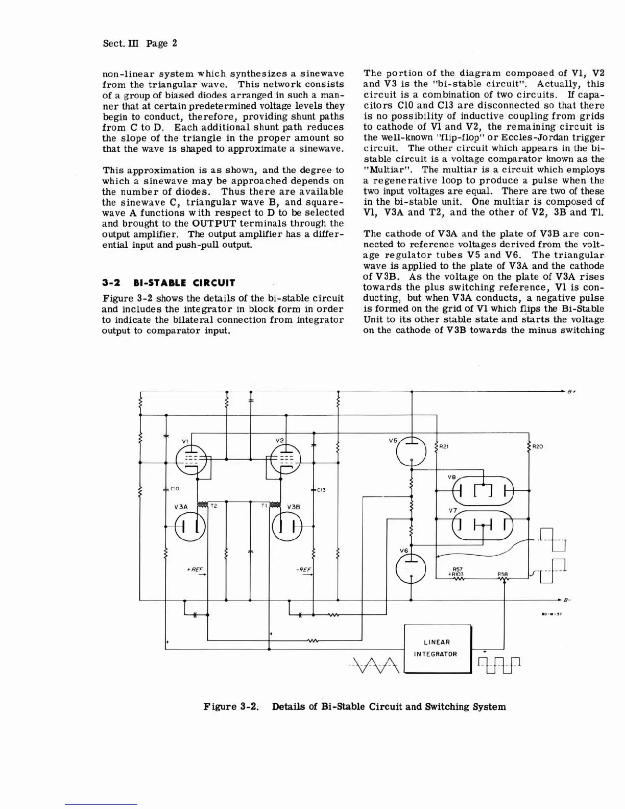
Figure 3-2 shows the details of the bi-stable circuit
and includes the integrator in block form in order
to indicate the bilateral connection from integrator
output to comparator input.
The portion of the diagram composed of
V1, V2
and V3 is the "bi-stable circuit". Actually, this
circuit
is
a combination of two circuits.
If
capa-
citors
C10 and C13 are disconnected so that there
is
no possibility of inductive coupling from grids
to cathode of
V1 and V2, the remaining circuit
is
the well-known "flip-flop" or Eccles-Jordan trigger
circuit. The other circuit which appears in the bi-
stable circuit
is
a voltage comparator known as the
"Multiar". The multiar
is
a circuit which employs
a regenerative loop to produce a pulse when the
two input voltages are equal. There are two
of
these
in the bi-stable unit. One multiar
is
composed of
V1,
V3A and T2, and the other of V2, 3B and T1.
The cathode of V3A and the plate of V3B are con-
nected to reference voltages derived from the volt-
age regulator tubes V5 and V6. The triangular.
wave
is
applied
to
the plate of V3A and the cathode
of
V3B. As the voltage on the plate of V3A rises
towards the plus switching reference,
V1
is
con-
ducting, but when V3A conducts, a negative pulse
is
formed on the grid of V1 which flips the Bi-Stable
Unit to its other stable state and starts the voltage
on the cathode of V3B towards the minus switching
Figure
3-2.
Details
of
Bi-Stable Circuit
and
Switching System
Bf
-
$
R20
4
I
SEC13
*
B-
.0-"-,,
LINEAR
-
~'j1133!
V3B
IE
INTEGRATOR
+REF
T
+
-
-REF
-
T
-
.-.
*