Sect.
III
Page
4
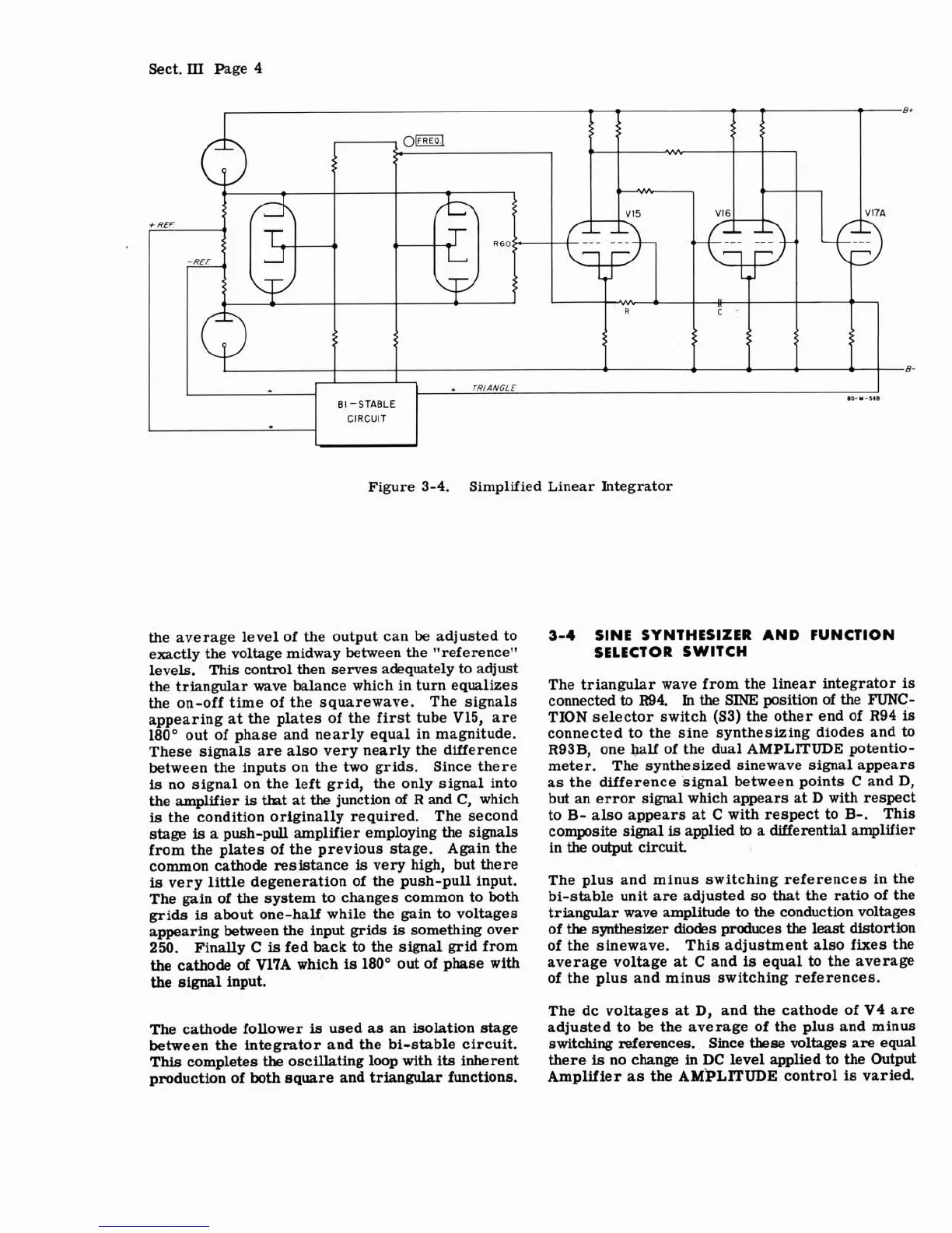
Figure 3-4. Simplified Linear Integrator
the average level of the output can be adjusted to
exactly the voltage midway between the "reference"
levels.
This
control then serves adequately to adjust
the triangular wave balance which in turn equalizes
the on-off time of the squarewave.
The signals
appearing at the plates of the first tube V15, are
180" out of phase and nearly equal in magnitude.
These signals are also very nearly the difference
between the inputs on the two grids. Since there
is
no signal on the left grid, the only signal into
the amplifier
is
that at
the
junction
of
R and C, which
is
the condition originally required. The second
stage
is
a push-pull amplifier employing the signals
from the plates of the previous stage. Again the
common cathode resistance
is
very high, but there
is
very little degeneration of the push-pull input.
The gain of the system to changes common to both
grids
is
about one-half while the gain to voltages
appearing between the input grids
is
something over
250. Finally C
is
fed back to the signal grid from
the cathode
of
V17A which
is
180" out of phase with
the signal input.
The cathode follower
is
used as an isolation stage
between the integrator and the bi-stable circuit.
This completes
the
oscillating loop with
its
inherent
production of both square and triangular functions.
3-4
SINE SYNTHESIZER AND FUNCTION
SELECT OR
SWITCH
The triangular wave from the linear integrator
is
connected
to
R94.
In
the
SINE position
of
the
FUNC.-
TION selector switch (53) the other end of R94
is
connected to the sine synthesizing diodes and
to
R93B, one half of the dual
AMPLITUDE
potentio-
meter. The synthesized
sinewave signal appears
as the difference signal between points C and
D,
but an error signal which appears at
D
with respect
to
B-
also appears at
C
with respect to
B-.
This
composite signal
is
applied
to
a differential amplifier
in the output circuit.
The plus and minus switching references in the
bi-stable unit are adjusted so that the ratio of the
triangular wave amplitude to the conduction voltages
of
the
synthesizer diodes produces
the
least distortion
of the sinewave. This adjustment also fixes the
average voltage at C and
is
equal
to
the average
of the plus and minus switching references.
The dc voltages
at
D, and the cathode of V4 are
adjusted to be the average of the plus and minus
switching references. Since
these
voltages are equal
there
is
no change in DC level applied to the Output
Amplifier
as
the AMPLITUDE control
is
varied.