Sect.
IV
Page 8
4-12
ADJUST SQUAREWAVE AMPLITUDE
Adjust control R63 to produce an output squarewave
with the same peak-to-peak amplitude as the sine
and triangular output waveforms.
4-13
FREQUENCY RATIO AND
CALIBRATION PROCEDURE
The following procedure
is
intended for use after
replacement of the Range Switch or any of the fre-
quency determining components on the Range Switch.
This procedure
is
also required following replace-
ment of frequency determining potentiometer R58.
7) Set the frequency dial to 0.8 and adjust control
R109 to obtain a period of 1250 milliseconds. Check
the setting made in step 6 and,
if
necessary, repeat
step 6.
I€
R109 has insufficient range, center the control me-
chanically and repeat steps
6
and 7. This will
electrically center the adjustment range of
R109
which can then
be
used to make any final adjustments.
1) Remove the cabinet or top and bottom instru-
ment covers.
2) Check that the upper and lower dial stops fall
about an equal distance outside the upper and lower
dial calibration marks. Correct the dial setting,
if
necessary,
by
rotating the dial on the dial mounting
hub. The dial stops and not the potentiometer me-
chanical stops should be limiting dial travel.
3)
Turn
the 202A on, set the line voltage to 115 volts,
turn the FUNCTION switch to "SQUARE", and allow
at least a
1 hour warm-up period.
4) Adjust power supply, then adjust DC Balance
and Distortion.
SHOWN
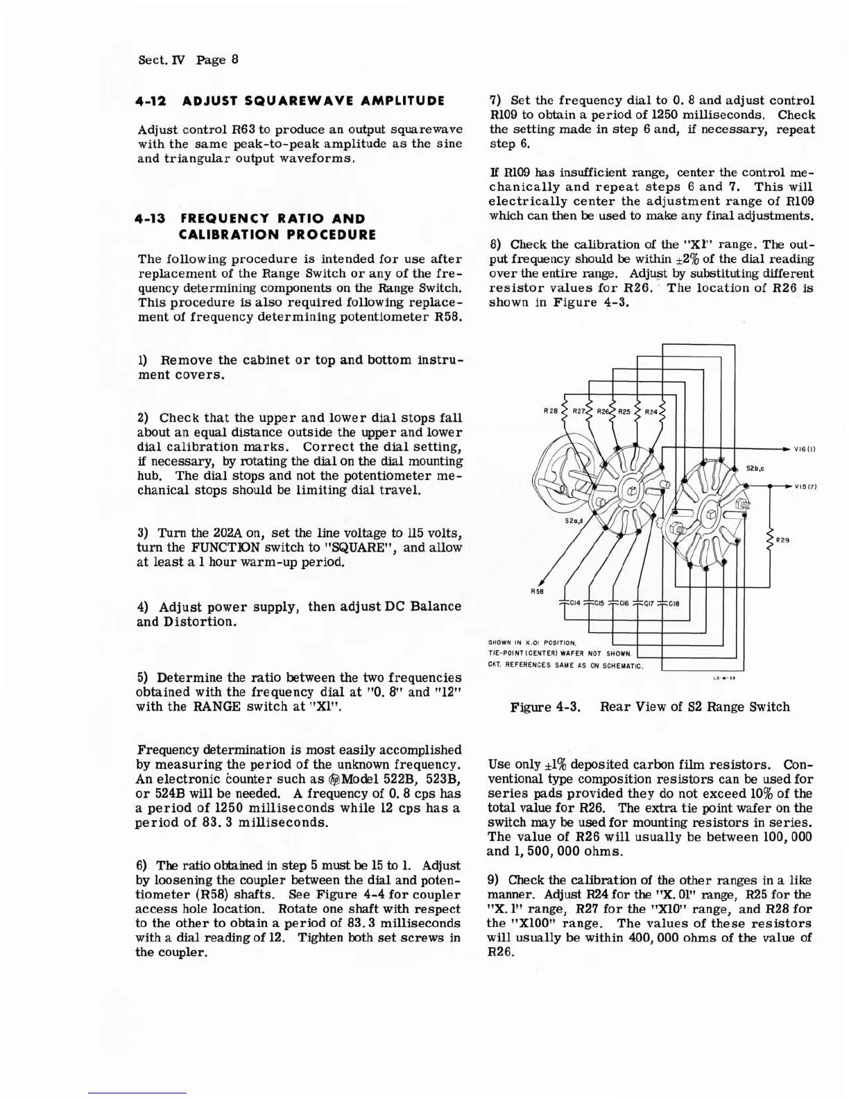
8)
Check the calibration of the "X1" range. The out-
put frequency should
be
within +2% of the dial reading
over the entire range. Adjust
by
substituting different
resistor values for R26. The location of R26
is
shown in Figure 4-3.
5) Determine the ratio between the two frequencies
obtained with the frequency dial at "0.8" and
"12"
with the RANGE switch at "Xl".
Frequency determination
is
most easily accomplished
by measuring the period of the unknown frequency.
An electronic
kounter such as @Model 522B, 523B,
or 524B will be needed. A frequency of
0.8
cps
has
a period of 1250 milliseconds while 12 cps has a
period of 83.3 milliseconds.
6)
The ratio obtained in step 5 must
be
15
to
1. Adjust
by loosening the coupler between the dial and poten-
tiometer
(R58) shafts. See Figure 4-4 for coupler
access hole location. Rotate one shaft with respect
to the other to obtain a period of 83.3 milliseconds
with a dial reading of
12.
Tighten both set screws in
the coupler.
X.01 POSITION.
TIE-POINT (CENTER) WAFER NOT SHOWN.
CKT.
REFERENCES SAME AS ON SCHEMATIC.
Figure 4-3.
Rear View of S2 Range Switch
Use only
*1%
deposited carbon film resistors. Con-
ventional type composition resistors can be used for
series pads provided they do not exceed
10% of the
total value for R26. The extra tie point wafer on the
switch may be used for mounting resistors in series.
The value of R26 will usually be between 100,000
and 1,500,000 ohms.
9) Check the calibration of the other ranges in a like
manner. Adjust R24 for
the
"X. 01" range, R25 for the
"X.
1"
range, R27 for the "Xl0" range, and R28 for
the
"X100" range. The values of these resistors
will usually be within 400,000 ohms of the value of
R26.