Sect.
111
Page
7
R44 R41
CZO
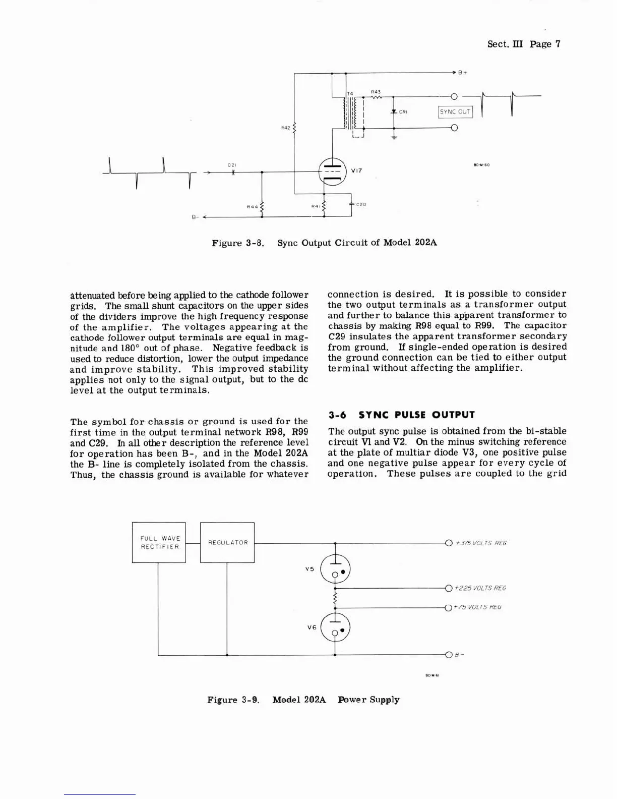
Figure 3-8.
Sync Output Circuit of Model 202A
attenuated before being applied to
the
cathode follower
grids. The small shunt capacitors on the upper sides
of the dividers improve the high frequency response
of the amplifier. The voltages appearing at the
cathode follower output terminals are equal in mag-
nitude and
180" out of phase. Negative feedback
is
used to reduce distortion, lower the output impedance
and improve stability. This improved stability
applies not only to the signal output, but to the dc
level at the output terminals.
The symbol for chassis or ground
is
used for the
first time in the output terminal network R98,
R99
and C29.
In
all other description the reference level
for operation has been
B-,
and in the Model 202A
the
B-
line
is
completely isolated from the chassis.
Thus, the chassis ground
is
available for whatever
connection
is
desired.
It
is
possible to consider
the two output terminals as a transformer output
and further to balance this apparent transformer to
chassis by making R98 equal to
R99. The capacitor
C29 insulates the apparent transformer secondary
from ground.
If
single-ended operation
is
desired
the ground connection can be tied to either output
terminal without affecting the amplifier.
3-6
SYNC PULSE OUTPUT
The output sync pulse
is
obtained from the bi-stable
circuit
V1
and V2.
On
the minus switching reference
at the plate of multiar diode V3, one positive pulse
and one negative pulse appear for every cycle of
operation. These pulses are coupled to the grid
REGULATOR
FlER
f
375
VOLTS
REG
.-0
+P25
VOLTS
REG
-
rs
REG
Figure 3-9. Model 202A Power Supply