Sect.
I'
Page 6
6) Set the
AMPLlTUDE control to minimum (max- 15) Switch the FUNCTION selector to TRIANGULAR
imum CCW) and move the voltmeter leads to the and note the voltmeter indication (0.5 on 0-1 scale
is
red OUTPUT terminals. "0 volts1'). Adjust R49 to reduce the dc voltage to
one-half
of
its
initial value, then adjust R51
to
remove
7) Adjust
R65, located behind a hole in the panel
the remaining
dc
voltage. The voltmeter should now
near the OUTPUT terminals, for an indication of
indicate
"0 volts1'.
"0 volts".
8) Set
R119, located near V1 and T2, to the middle 16) Set the FUNCTION selector to SINE and adjust
of
its
range.
R118 for a voltmeter indication of
"0 volts".
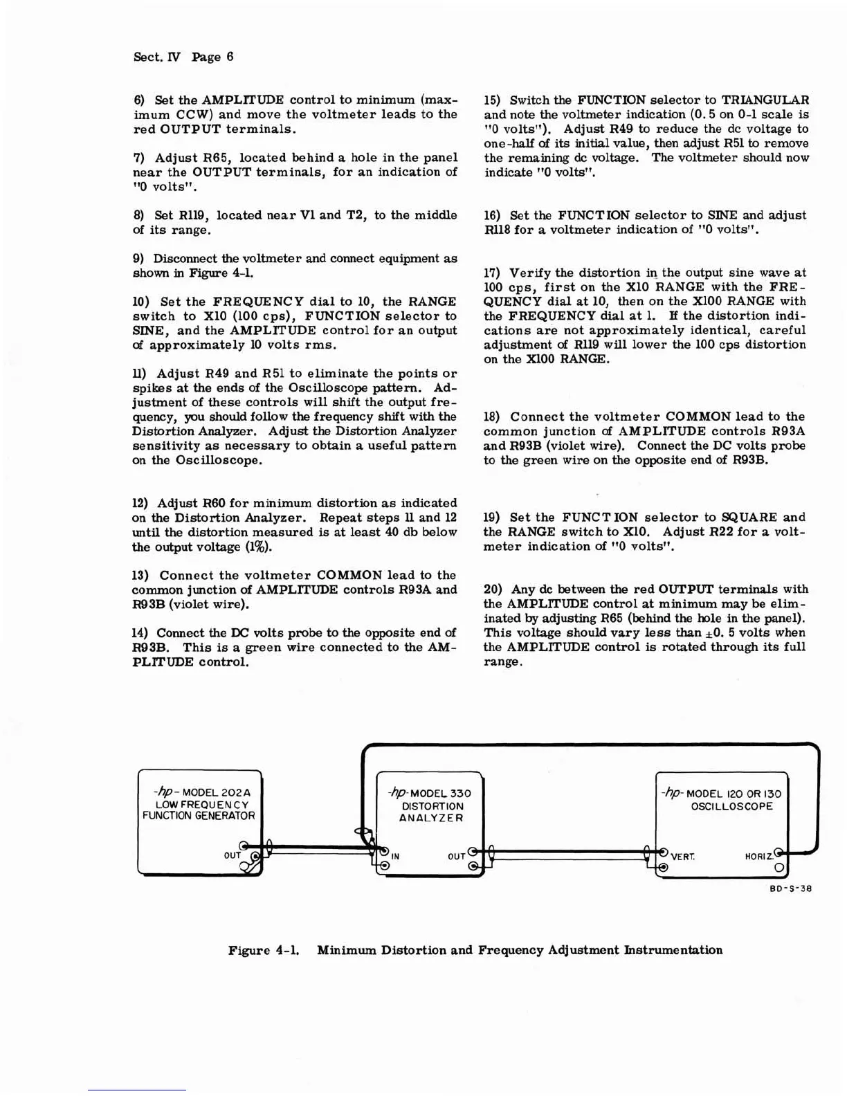
9) Disconnect the voltmeter and connect equipment as
shown in Figure 4-1.
10) Set the FREQUENCY dial to 10, the RANGE
switch to
X10 (100 cps), FUNCTION selector to
SINE, and the AMPLITUDE control for an output
of
approximately 10 volts rms.
U)
Adjust R49 and R51 to eliminate the points or
spikes at the ends of the Oscilloscope pattern. Ad-
justment of these controls will shift the output
fre-
quenc y, you should follow the frequency shift with the
Distortion Analyzer. Adjust the Distortion Analyzer
sensitivity as necessary to obtain a useful pattern
on the Oscilloscope.
17) Verify the distortion in the output sine wave at
100 cps,
first
on the X10 RANGE with the FRE-
QUENCY dial at 10, then on the XlOO RANGE with
the FREQUENCY dial
at
1.
I£
the distortion indi-
cations are not approximately identical, careful
adjustment
of
R119 will lower the 100 cps distortion
on the XlOO RANGE.
18) Connect the voltmeter COMMON lead to the
common junction
of
AMPLITUDE controls R93A
and R93B (violet wire). Connect the DC volts probe
to the green wire on the opposite end of
R93B.
12) Adjust R60 for minimum distortion
as
indicated
on the Distortion Analyzer. Repeat steps 11 and 12
19) Set the FUNCT ION selector to SQUARE and
until the distortion measured
is
at least 40 db below
the RANGE switch to
X10. Adjust R22 for
a
volt-
the output voltage (1%).
meter indication
of
"0 volts1'.
13) Connect the voltmeter COMMON lead to the
common junction
of
AMPLlTUDE controls R93A and
20) Any dc between the red
OUTPUT
terminals with
R93B (violet wire).
the AMPLITUDE control
at
minimum may
be
elim-
inated
by
adjusting R65 (behind the hole in the panel).
14) Connect the
DC
volts probe to the opposite end of
This voltage should vary less than
kO.
5 volts when
R93B. This
is
a
green wire connected to the AM-
the AMPLITUDE control
is
rotated through
its
full
PLITUDE control. range.
r
\
f
1
r
\
,
1
-hp-
MODEL 202A
-hp-
MODEL 330
-hp-
MODEL 120 OR
130
LOW FREQUENCY DISTORTION OSCILLOSCOPE
FUNCTION GENERATOR ANALYZER
HORIZ.@
BD-S-38
Figure 4-1.
Minimum Distortion and Frequency Adjustment
hstrumentation