IGMP proxy forwarding
When a network has a border router connecting a PIM-SM domain to a PIM-DM domain, the
routers that are completely within the PIM-DM domain have no way to discover multicast flows in
the PIM-SM domain. When an IGMP join occurs on a router entirely within the PIM-DM domain
for a flow that originates within the PIM-SM domain, it is never forwarded to the PIM-SM domain.
The IGMP proxy is a way to propagate IGMP joins across router boundaries. The proxy triggers
the boundary router connected to a PIM-SM domain to query for multicast flows and forward them
to the PIM-DM domain. IGMP needs to be configured on all VLAN interfaces on which the proxy
is to be forwarded or received, and PIM-DM must be running for the traffic to be forwarded.
You can configure an IGMP proxy on a selected VLAN that will forward IP joins (reports) and
IGMP leaves to the upstream border router between the two multicast domains. You must specify
the VLANs on which the proxy is enabled as well as the address of the border router to which the
joins are forwarded.
How IGMP proxy forwarding works
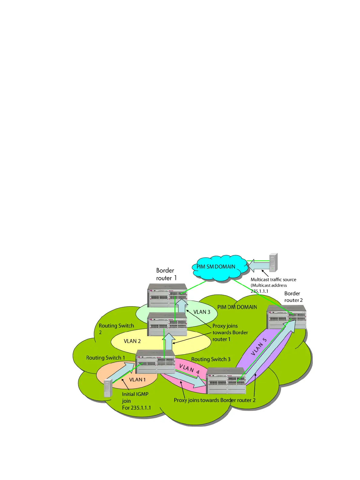
The following steps illustrate how to flood a flow from the PIM-SM domain into the PIM-DM domain
when an IGMP join for that flow occurs in the PIM-DM domain. See Figure 2.
1. Configure Routing Switch 1 with the IGMP proxy forwarding function to forward joins toward
Border Router 1; in addition, configure Routing Switch 1 to forward joins from VLAN 1 toward
Border Router 2, as is VLAN 4 on Routing Switch 3.
2. Configure VLAN 2 on Routing Switch 2 to forward joins toward Border Router 1.
3. When the host connected in VLAN 1 issues an IGMP join for multicast address 235.1.1.1,
the join is proxied by Routing Switch 1 onto VLAN 2 and onto VLAN 4. The routing information
table in Routing Switch 1 indicates that the packet to Border Router 1 and Border Router 2 is
on VLAN 2 and VLAN 4, respectively.
Figure 2 IGMP proxy example
4. Routing Switch 2 then proxies the IGMP join into VLAN 3, which is connected to Border Router
1.
IGMP proxy forwarding 19
 Loading...