TM 11-6625-1576-15
Model 333A/334A
Section IV
Paragraphs 4-26 to 4-27 and Figure 4-3
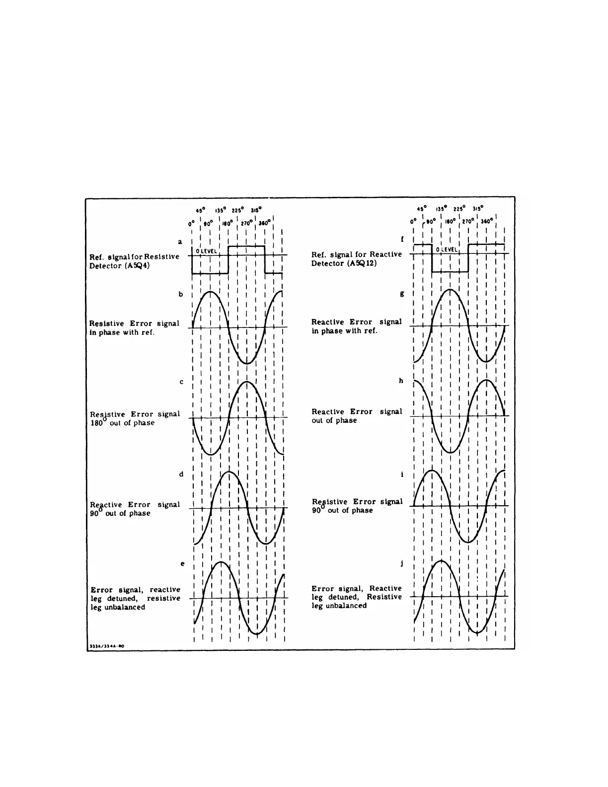
4-26. The operation of the reactive branch control loop
is similar to that of the resistive branch. The phase
delay circuit (Figure 6-6), A5Q15, A5Q16, S4AF and
S4C1 through S4C5, shifts the reference voltage 90º,
as shown in Figure 4-3f.
This makes the detector
A5Q12 sensitive to components of the bridge error
signal that are 90° out of phase (g and h). The output
of the lamp driver, Q14, controls the brilliance of
A6DS2, which varies the resistance of A6V2 through
A6V5 to tune the branches of the reactive leg. Deck
AR of the FREQUENCY RANGE switch, S4, switches
A5R56 in parallel with A5R55 on the top three frequency
ranges.
A6DS2 will become brighter, and lower the
resistance of A6V2 through A6V5, making variation
in resistance less than on the two lower ranges.
However, less variation in resistance is needed to
tune the leg, because the impedance in the reactive leg
becomes progressively less as the higher frequency
ranges are selected.
4-27. Any error signal that is not an integral multiple
of 90 is the result of the reactive leg of the bridge
being detuned, and the resistive leg being unbalanced.
.
For example, an error signal that is 45º out of phase
(Figure 4-3e and j) will result in outputs from both
detectors to tune the bridge and reject the fundamental.
Figure 4-3. Reference and Error Phase Relationship
4-3
 Loading...


