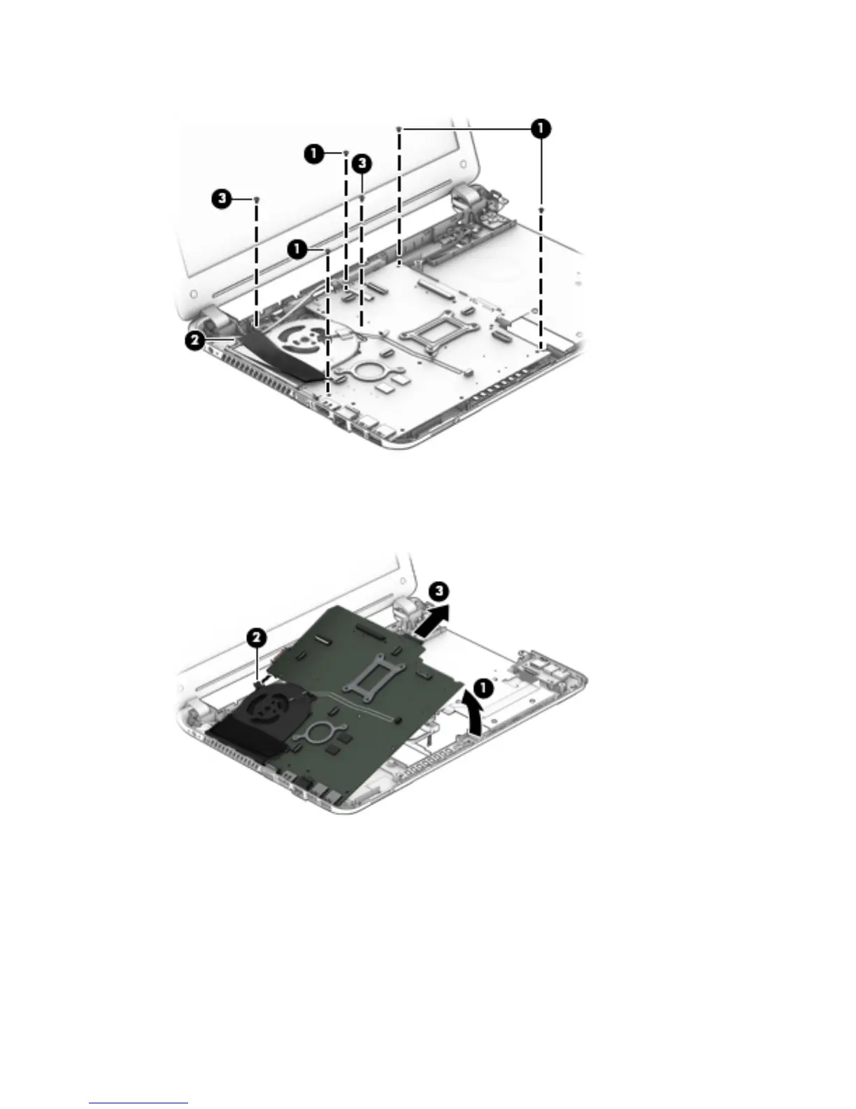
6. Remove the four Philllips PM2.5×4.5 screws (3) that secure the system board to the base enclosure.
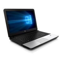
7. Lift up on the right side of the system board (1) until it rests at an angle.
8. Disconnect the power connector cable (2) from the system board.
9. Remove the system board (3) by sliding it up and to the right at an angle.
Reverse this procedure to install the system board.
56 Chapter 6 Removal and replacement procedures for Authorized Service Provider parts