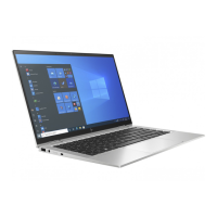
2. Release the wireless antenna cables from the routing clips (2) and channel built into the
base enclosure.
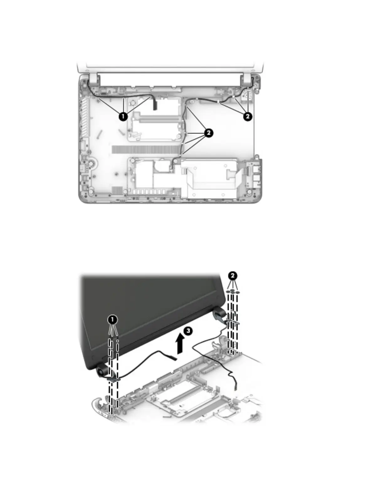
3. Remove the three Phillips PM2.5×4.5 screws (1) that secure the display assembly left hinge to the
base enclosure.
4. Remove the four Phillips PM2.5×3.25 broad head screws (2) that secure the display assembly
right hinge to the base enclosure.
5. Remove the display assembly (3).
Component replacement procedures
95

 Loading...