Section lll
capacitarrce on both channels.
The effects
of source
impedance
can
be
nrininlized. horvever.
by thc use of
10
I{egohnr l0:l divider
probr.'r
(+p-
I000.1A)
which reduce
the efl'ective shunl eapacilance lo approxirnately l0
pF.
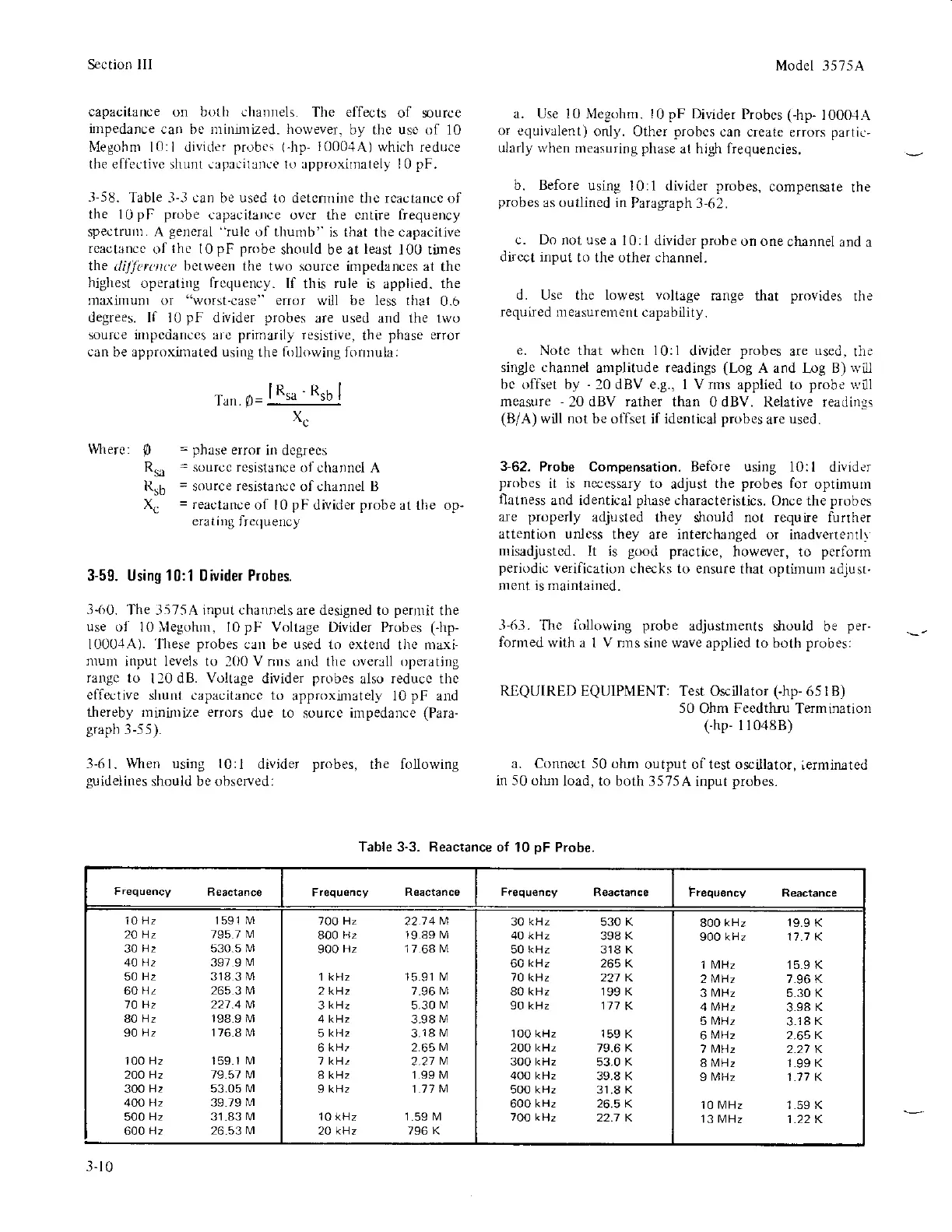
-l-58.
Table
-l-3
can
be
used
to detcmlite thc rcactance of
the 10pF
probe
capacitalce ovcr the cntire lrequency
spectrurn. A
gelleral "rulc
of thuntb"
is that the capacitive
rcactarcc
oI
the
I0
pF probe
should be at
least
100 tines
the
di.lJcrurc
bctweerl the
two source irnpedances at
thc
highest
operali
g frcquency.
If
this
rule
is applied. the
n&ximuDl or
"worst-case" eruor will be less that
0.6
degrees. If 10
pF
divider
probes
are used and the 1wo
source ittpcdarces are
primarily
resistive,
the
phase
error
can
be approxirnated
using
the
hrliorving
fornrula:
Tun.
P=
lR'o
-
Rsb
I
xc
=
phase
error
in dcgrees
=
sourcc resistance
of channel A
=
source resistanoc ofchannel B
=
reactance
of
l0
pF
divider
probe
at the op-
erati
g
Irequency
3-59. Using
10:1
Divider Probes.
3-(r0.
'l'he
3575A input chalnels are
designed to
pernrit
the
use
o1 l0llegohm, I0pF
Voltage Divider Probes
(Jrp-
1000.1A). Ilrese
probes
can be used to extcnd
the maxi-
munl
input levels to
l(X)
V nlls
and the overlll
operatjng
rargc to
120 dB.
Voltage
divider
probes
also
reducc the
effective
shulll capacitancc to
approxintately l0pF- al-Id
thereby rninirDize errors
due to
source
impedance
(Para-
graph
3-55).
3-61. When using l0:l
divider
probes,
the following
guideliltes
should be
observed:
Model 3575A
a. Use l0 l\{egohnr. l0
pF
Divider
Probcs (-hp-
1000-lA
or equivirlent)
only. Other
probcs
can create
errors
partie-
ularly u,hen
measuring
phase
at high Irequencies,
b. Before
using l0:1
divider
probes,
compensate
the
probes
ar outlincd in
Paragraph J-rr2.
c. Do
not
use
a l0:l divider
probe
on one
channel and
a
dircct input
to the other channel.
d. Use the lowest voltage
range
that
provides
the
required measuretrent
capability.
e.
Notc that whcn 10:1
divider
probes
are
used.
tlie
single channel
arrplitude readings
(Log
A and l.og B)
rvill
bc offset by
-
20dBV
e.g.,
I Vrnrs applied
to
probe
\r l
measure
-
20 dBV
rather
than 0 dBV. Relative readings
(B/A)
will
not
be olfset if identical
probes
are
used.
3-62.
Probe Compensation. Before using
10:l divider
probes
it is
necessary
to
adjust
the
probes
for
optimunr
flatness
and identical
pluse
characteristics.
Once the
probss
are
properly
adjusted they should not require furrher
attention unless
they are interclutrged or
inadvertentl\
misadjustcd.
It is
good practice,
however, to
perfornr
periodic
verificatiorl
checks to ensure
that opthturr adjusr.
lnent is maintained.
-l
6-1.
'[hc
following
probe
adjustments
s]rould be
per-
formed
with a
I
V nns
sine wave applied to both
probes:
RIQUIRED EQUIPMENT: Test Osrillator
(-hp-
651B)
50
Ohm
Feedthru
Terminatiorl
thp-
I1048B)
a. Connect 50 ohnr
output of test oscillator,
ierminnted
in 50 olun
load, to both 3575A
input
probes.
Wrerc:
p
Rsa
Rrb
\
Table 3.3. Reactance
of 10
pF
Probe.
Frequency
Beactance
Frequency
Reactance
Freq,-rency Reactance
10
Hz 1591 M
20 Hz 1951
M
30
H2 530.5 M
40 Hz 397
9
lvl
50
Hz 318
3
l\4
60Hz
26s3M
10 Hz 221.4 M
80
Hz 198.9 M
90
Hz 1768M
100
Hz
159.1
M
2OO
Hz 19.51 M
300
Hz 53.05 l\,4
400 Hz
39.79
N4
500
Hz 31.83 M
600 Hz 26 531\,4
TOO Hz
2214
M
800
H2 19 89 M
900
Hz 17
68
M
1 kHz 15.91 lvl
2kHz 7.96 M
3
kHz
5.30
lvl
4 kHz
3.98
M
5
kHz
3.18lvl
6
kHz 2.65
M
I kHz
2.21
M
I kH, 1.99 M
9 kHz 1 .11
M
10 kHz 1.59 M
2A kHz 796 K
30
kHz
530 K
40 k{z
398 K
50 kHz 318 K
60
kHz
265 K
70 kHz 22t K
80 kHz 199 K
90 kHz 171
K
1O0 kHz 159
K
2OOkHz
79.6 K
3o0 kHz
53.0 K
4oo kHz
39.8 K
5OO kHz 31.8 K
600 kHz 26.5 K
7Oo kH, 2? t K
800
kHz
19.9 K
900 kHz 11.1 K
'l
MHz
15.9 K
2
MHz
7.96 K
3
MHz
5.30 K
4
MHz
3.98
K
5
[4Hz
3.18
K
6ltrHz
2.65 K
1 MHz 2.21 K
I
[4Hz
1.99 K
9
MHz
1.17 K
10
MHz
1.59 K
13 MHz
1.22 K
3.1
0