N4odel 3575A
b.
Set
thc
-15754
controls
as follows:
DISPLAY
,... AMPLITUDE
Volragc llalgc
0.1
mV to
I
V
(both
chunnels)
A,\IPLI fliDtr FUNCTION. .. . . . .. .. A
FREQUEN'Y RAN(]F]
.. -
.. , IOO. I N,I
PHASE
RLFLITENCE , ... , ... ,
,
... A
c. Set
the test
oscillator for an output
of
I
Vnrls.
100
Hz.
d.
Rccord the channel A
amplitude
reading:-dBV.
e.
Estrblislr
J
refcrcnce Icvel
oll
the rrlcter
of the test
oscillator
rird
use
the
oscillator u
plitude
control
to
maintairl this
reaercnce
level whclevcr the
frequency is
varied-
f. Set
the rest oscillator
frc.luency to
1 'lHz.
g.
Adjusl
the .harnel A
probc for
the sarne
reading
recorded in Step
d.
h. Repeat Steps
c through
I
until optirtum adjustment
is ohtrined.
i.
Sct
lhe tesl
()scilLxtor
1rc(luency
to 1.5
kH1.
j.
Scl thc
-1575A
DISPLAY swilcl) to
PflASE.
k.
Adjust
the chennel
B
probe tirr
l
phase reading ol0
degrees
10.i
degees.
l. ser
rhc .r575A DISPLAY switch
to
AiUI')LII
LIDFI: set
the AN1PLITUDI,
FU\C.TION swilch
to B/A.
]n. Set
th0 tcst os-.iilator
fre(luency to I MHz.
n. The B/A
reading should be 0
dB
10.1
dB. ll
it is
not.
perlorn
the
following:
l) Repeat
thc
probe
adjustmcnt
Procedure.
1) Rcplace
the
probes
one at a tirnc
to detennine
if
the
problcrn
is causcd
by
frulty
probes.
3) Perform
tl're adjustment
procedures outlined
in
Section V.
3-54.0PTr0NS.
3-65. 0
ption
001.
3-66. The 3575A Option 001 is
equipped with dual
panel
meters to
provide
sinrultuneous anplitude
and
phase
presentati{)ns.
This
ilptiorL is aiso
equippcd
rvith trvo arulog
outputs to
permit
arnplitude
vs.
phase plotting.
3-67. In the .1575A Option
001. the left-lund
(facing
the
front
panel) panel
mcter
rlways ildicates anrplitude. This
palel
rneter is
controlled by the AMPLITUDE
FUNCTION
switch
which,
as ir the standard
l{odel .1575A,
pernrits
selection
of
Log
A. Log B or LoB ts/A.
Section
III
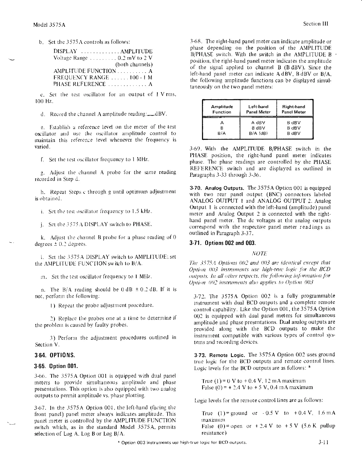
3-(r8.
Thc
rightJrand
panel
meter can indicate
amplitude or
phase
depending
on
the
position
of the
/LVPLITUDE
B/PHASI
srvitch.
With
the switch in the ANIPLITUDE
B
positioD.
the
right-hand panel
meter indicates
the anplitude
of the
signai applied to channel B
(B
dBV).
Since the
left-hand panel
neter can indicate
AdBV.
BdBV
or ts/A,
the
foliowiDg
amplitude functions
can be displayed simul-
taneously on the two
panel
metersl
LeI!-hand
Panel M€ter
Right-hand
B
BIA
A dBV
B
dBV
B/A
(d8)
B
dBV
B
dBV
B dBV
-l-69.
With
the
AMPLITUDE
B/PHASE
switch in the
PHASE
position,
the right-hand
panel
meter indicates
phase.
The
phase
readings
are controlled by the PHASE
REFERBNCE
switch and arc displayed
as outlined in
l'aragraphs
-j--13
through .1-.36.
3-70.
Analog Outputs.
The 3575A Option
001 is
equipped
with two rear
panel
output
(BNC)
connectors labeled
ANALOG OUTPUT I and ANALOG OUTPUT
2. Analog
Output
I
is connected with the left-hand
(amplitude) panel
meter
and Analog Output 2 is connected with the right-
hand pancl
rncter.
The dc
voltages
at the analog outputs
correspond
with the
respective panel
meter readings
as
outlined in Paragraph
3-37.
3-71. 0ptions
002 and 003.
,\.oTf.
Thc
1575.1
O|ti)fis 00: attLl
|l)i arc iLlafili(al arq'pl
tltat
Optiott
l)0-) itstntDtents usc ltigbtnrL'
htgit
liu
tlrc BCD
t)L!tputs. In all otlrcr respects,
thc
.ll
httritt< itt/rtttttotitrt
l'ot
)l)tu)n
l)l): ittstruDtcDls dlso epplias
tt Olttirtt
l)03
-.1'71.
Ttre 3575A
Option 002
is a
lully
progammable
instrument
with dual
BCD
oulputs and a coinplete
remote
control capabi.lity.
Like
the Option 001,
the
3575A
Option
001 is
equipped with dual
panel meters for sinlultaneous
amplitude
and
phase
presentations.
Dral arBlog
oulputs are
provided
along with the
BCD outputs
to make
the
instrument cunpatible
with
various types of
control sys-
tems
and
recording devices.
3-73. Remote Logic.
Tire
3575A Option 002
uses
ground
lruc
logic for
the llCD outputs attd
remote control
lines.
l-ogic levels for the B('D
outputs
are
as follorvs:
*
True
(l)
= 0
V to
+
0.4
V. l2 mA maxirnunr
Falsc
(0)=
+
1..1
V
to
+
5 V. 0.4
lnA maxirnurlt
L-ogic levels
for the rclnote control
lines are rs
follows:
True
(1)=ground
or
-0.5V
to
+0.4 V. L6 rnA
lnaxtnunr
False
(0)=open or
+1.4V
to
+5V (5.6 K
puuup
resistance )
*
Option
003 instruments
use high-true loqic
ior
BCD outputs. .l-l l