Section
llI
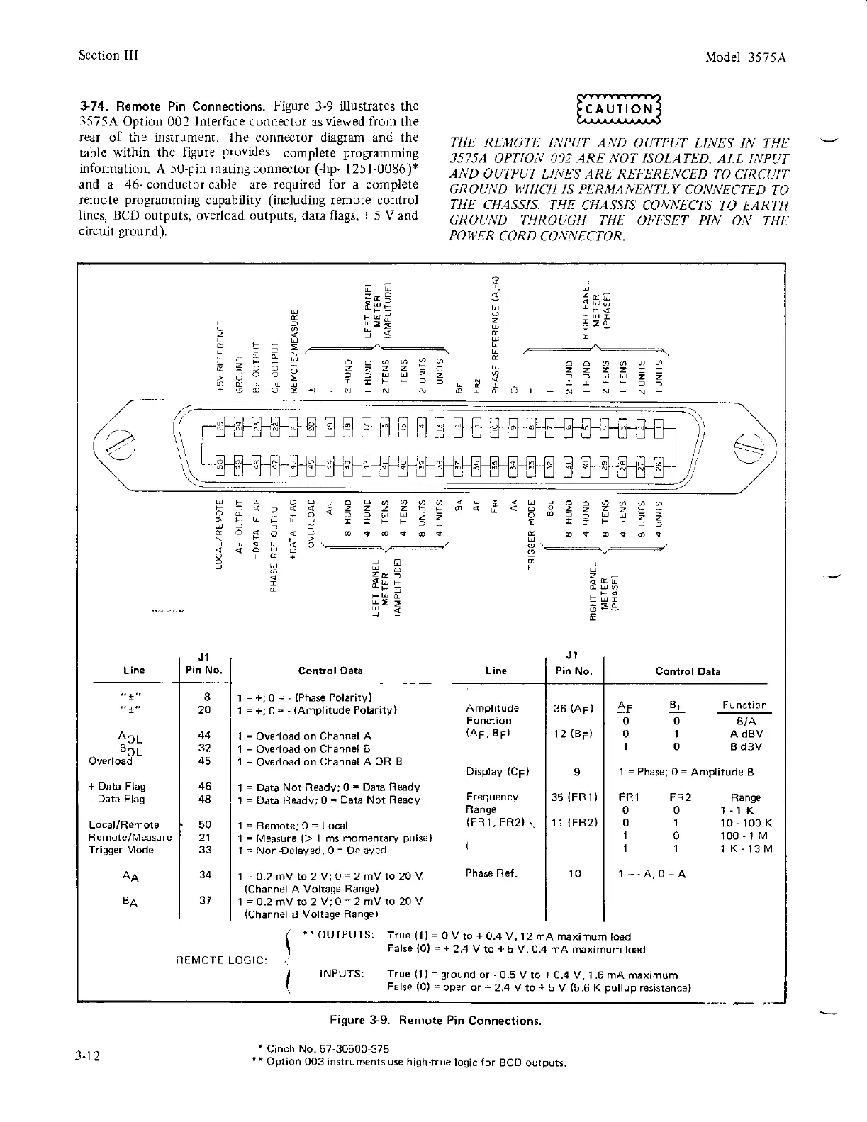
374. Bemote Pin Connections. Figure 3-9
illustrates
the
3575A
Option 001
Interface
connector as
viewed from
the
rear of the instrument. The connector diagram and the
table
within the figure
provides
s6mplgls
programming
infonnation.
A
5o-pin rilating connector
(-hp-
l25t-0086)+
and a 46- conductor cable are requircd for a complete
remote
prograinmirg
capability
(including
remote control
Iines,
BCD outputs, overload outputs,
data
flags,
+
5
V
and
circuit
ground).
Model
35 75A
THE REJI.IOTT: INPUT
AND
OUTPUT I.INES IN THE
3575A
OPTION OO2
ARE NOT ISOLATED.
AI.L INPUT
AND
OUTPUT LINES ARE REFE:RENCED TO CIRCI]IT
GROUND
'I)HICH
IS PERMANENTT,Y
CONNECTED
TO
TIIE CHASSIS.
THE CHASSIS CONNECTS
TO EARTI{
GROUND
THROUGH THE
OFF'SET PIN ON THL'
PO
II
E R-CO RD
CON N E CTO
R.
:6r
i;
I
g;s
i9
)
-5.5
4
9-
(
I
6=g
;,
zf,a
Eqi
--
lE9
1<
5 5;n
=z
lIFtsTT
-Fg
6>g
n
]O
!3
s
a
9
2z
ar:JUU==
8r
0
I
0
4E
0
0
I
1=
FRl FR2
00
01
10
11
J1
Pin No.
Control
Data
J1
Pin
No. Control Data
AoL
BoL
Overload
+
Data Flag
-
Data Flag
Trigger N4ode
Amplilude
(Ap,85)
Display
(CF)
Range
(FR1,FR2}
,.
(
Phase
Ret.
36
lAF)
12
(BF)
I
35
{FR1)
11
lFR2)
Function
B/A
A dBV
B dBV
Range
1-'t K
10-100K
100-1M
1K-131\r1
20
44
45
46
48
50
21
33
34
31BA
1
=
+;
0
=
-
{phase
potarity)
1
=
+,0=
-
(Amplitude
Polariry)
1
=
Overload
on Channel A
1
=
Ov€rload on Channel
I
1
= Overload
on Channel
A OR B
1 =
Data Not Ready;0
=
Data R&rdy
1
=
Data Ready,0
=
Data Not Ready
1=Remote;0=Loc€l
1
=
N,4easure
{>
1 ms
rnomentary
pulse}
I
=
Non-Delayed, 0
=
Delayed
1 =0.2
mVto 2 V;0= 2
mVto
20
V
(Channel
A Voltage
Range)
1
=0.2
mV lo 2
V;0
=2
mV ro 20 V
(Channel
B
Volrage Range)
=
Phase; 0
= Amplitude B
REMOIE LOG IC:
.'
OUTPUTS: True
11l=0Vto+0.4V,12mAmaximumtoad
False
(O)
=
+
23 V to
+
5 V,0.4 mA maximum
toad
INPUTS: True
(l
)
=
ground
or
,0.5
V to
+
O.4 V,
1 .6
mA maximum
False
(0)
= open or
+
2.4 V to
+
5
V
{5.6
K
pullup
resistance)
Figure
3-9. Remote Pin
Connections.
'
Cinch No. 57-30500'375
**
Option
003 instruments use high-true
logic {or
BCD ourputs.
3-12