Sectlorr l
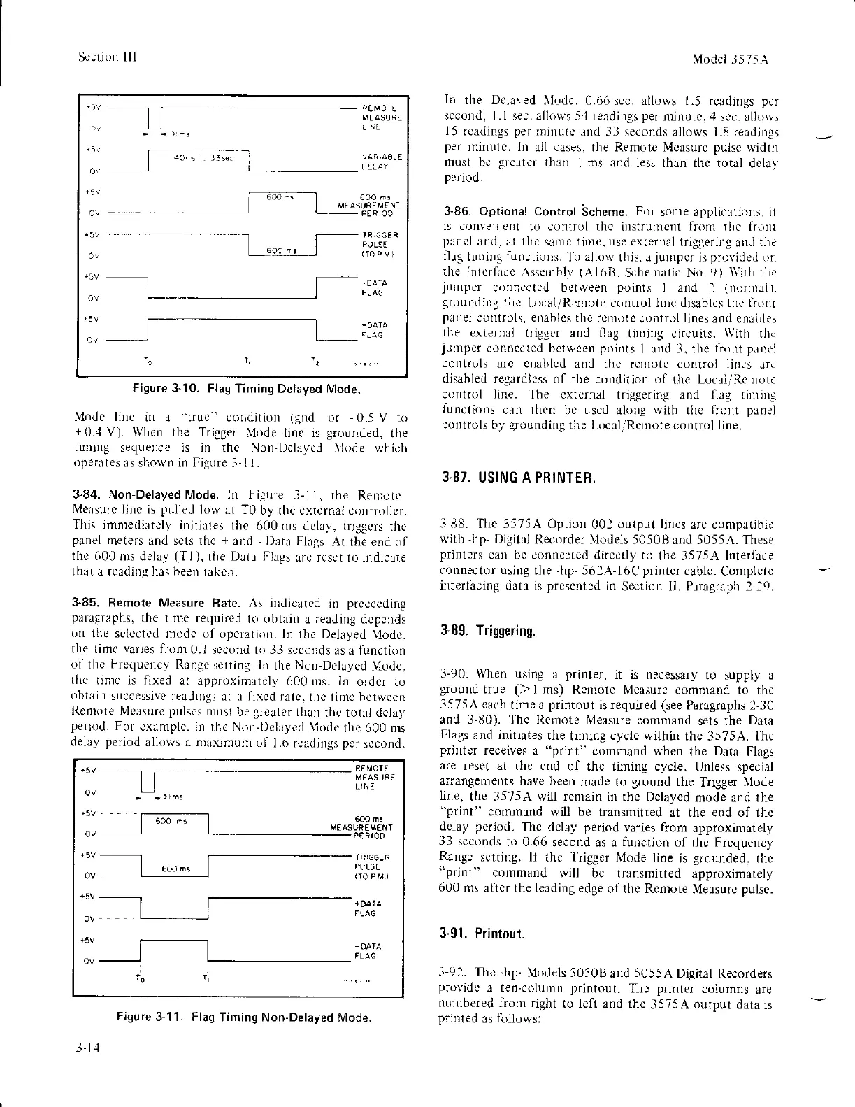
Figure 3-10.
Flag Timing
Delayed Mode.
lVlodc line
in a
'true"
conditbn
(g|d.
or
-0.5V
to
+0..1
V). When
the Trigger
trlode linc is
grounded.
the
tirning
sequelce is in
the Non-Dela1,cd
\lode
$,hicil
operates
as shown in Figure
3- I l
3"84. Non-Delayed
Mode. In
Figure
3-1i,
the
Rernote
Measurc
line is
pulled
lorv at T0
by the cxtcrnal
coDtrollsr.
This
immcdirtcly initiates
the 600rrs
dclay,
trjggcrs thc
panel
meters ar)d
sets the
+
and
-
l)ata Flags.
Ar
the end ol'
the 600
ms dclay
(Tl).
lhe
Dlla Fhgs
irre rcset to indicate
thrt a lcading has
been litkcn.
385,
Remote Measure
Rate.
As
illdicated
in
prcceeding
paragraphs,
the lime required
lo obtxin
a
reading
depends
on
thc sclectcd
mode ol operation.
lo the Delayed
Modc.
the tjmc
varies
from
0.1
sccond to 33 scconds
as a functjon
of
the
Frcquency
Range
serting. Il
the
Non-Dclayed
Nlode.
the
tinrc is fixed
at approximatcl)
600 ms. In
order
to
obtain
successivc readings
al I lixed rate.
tlte tinre
betwect)
Rcmote
Nleasurc
pulscs
musl
be
greater
than
the tottl delay
peLiod.
For
cxample.
in the Nol,Dehycd
Nlodc
the 600 ms
delay
period
allows
a
maximum
ol
1.6 rcadings
per
sccond.
Modet
1575A
In
rhe Dclayed
}lodc.0.66sec.
allows 1.5 readings
per
second,
l.l sec. allrws 5-1 readings
per
minutc,
zl
sec. allows
l5
readings
per
irillLrt.
and 33
seconds allows 1.8 readings
per
minulc. In
all
cases,
the Remotc Measure
pulse
width
must
be
greilter
than
1ms aod less than thc total
dela)
period.
3-86.
Oprional
Control
'Scheme.
For
sonre applications. il
is convenienl
to conlrol the
instrunrent
from
tirc front
plncl
und. Jt tha sanrc iirne. use exteroal
triggeritg
and
the
flag
tirr]ng
funclioDs.
To allow this. a
junlper
is
provide,l
on
the Interface
Assembl\'
(Al()It.
S,0hematic No.9).
\\'ilh
rh.
juinper
connecled betiveen
points
I and I
(norilJi).
grounding
thc
[-ocal,i Re]note control liDc disables the lronr
panel
corltrois, enables
thc rqlnote
control
lines
and enlbles
the external
trigBsr and flag
tirning circuits.
With
lh.
jumper
connccted betwcen
points
I a d
-1.
thc
tio
t
pJ|!'i
controls
arc
enabled
and tlic rcnrote
control
lin('s
Jr.
disabled
regardlcss of the condition of
the Local,/lleinole
control line.
The cxternal triggering
and
fiag
ti]]ting
lunctions
can then
be
uscd
alolrg
with
tlte
frollt pJnel
controls
by
grounding
the LocaliRcrnote control line.
3.87.
USING A PRINTER.
3-88.
The 3575A Option
001
output
lines are compaLlb['
with,hp-
Dgital
Recorder illodels 50508
alid 5055A.
'fhese
printers
cari
be connected directly to
the 3575A Interfice
connector
usillg the
-hp'
56:A-l6C
printer
cable.
Complete
interlacirg data
is
prcsentcd
in
Sectiorl II, Paragraph l-la.
3-89. Triggering.
3-90. \Vhen using
a
printer,
it is necessary
to supply a
gound-true
()
I ms) Remote
Measure commald to the
3575A
each
time a
printout
is requted (see
Paragraphs 2-30
and 3-80).
The
Remote Nleasure conrmand
sets the
Data
Flags
and initiates
the
timing
cycle within
the
3575A.
The
printer
receiyes a
"print"
command when
the
Data
Flags
are
reset at the cnd
of the
tining cycle. Unless special
arrange[rents have
been
made to
ground
the
Trigger
N,lode
Iine,
the 3575A will re
ain in the Delayed
mode
and
the
"print"
command will
be transmitted
at the end of
the
delay period,
The delay
period
varies
from
approximately
33
scconds
to 0.66
second as a
function
of
the
Frequency
Rlnge
sctting. If
the
Trigger
Mode
line
is
grounded,
the
"prin1"
command
wili be transmitted
approximately
600
ms al'tcr the leading
edge
of the Rcnlote
Measure
pulse.
3-91. Printout.
-l-92. Thc
-hp-
Nlodels 505013
and
5055A
Digital
Recorders
providc
a ten-column
priltout.
Thc
printer
columns
are
nurubered
frollr right
to
left and the
3575A
output
data
is
printed
as
follows:
_5!
1!
r5l
0n
IEMOlE
MEASUFE
i
\E
'
. ,J
-
.----l
600 tr !
v!
d
cupF
[/
t
N-
'
eaP-'
ar
+5v
15V
PJLSE
OV
|5v
OV
ov
+5V
OV
+5v
ov
MEASUFEM€NT
PI]L5E
Figure
3-11. Flag
Timing Non-Delayed
Mode.
l.l
,1