Section lV
which
goes
to a
high (1)
state. The X current sinl
remains
off because
Q',
T'and \{r'are all
high.
The
Y current
sink
remains off
boausc
I'ls
-
0
artd T'
=
I .
.l'.16.
With
a
phase
difference
of
-
120 degrees applied
to
the inputs,
Q
goes
low, B channel is iilverted and the
phase
differencc applicd to
the
phase
dctectors
is
+60
degrees.
The rcsulting
phase
detector
output
is
-
1.2 Vdc. [n
this
case, the Xcurent sinkiscutoff bcause
Q'=
l(Q=0),
M,
=
0 and T'
=
I
(T
=
0). Thc
Y currcnt sink is cut off
because Ms=0 and T'= I
(T=0).
The
rcsult is e correct
pluse
readilg
with
no olTsets requircd. The Pltase Control
Logic operates in the sanre nranner
for
ali
negativc
phase
differences
greater
tharl
'90
dcgrccs
ard less than
-192
degrees.
447. lf the
phase
readiDg exceeds
-
192 degrecs
(
1.92 Vdc). M'
goes
high
and a set
comnland is applied to
the
"Nl"
storage
element. Both current sinks are
the
gated
on
(xs
outlined in
Paragraph
.1-.14)
artd the
phase reading
changes liorn
"
192 degrees to
+
168 degrees. This
is
sirnilar
to the
+
191
degree
conditior whcre both cufient sinks
ar!'
gated
off
a|d the
reading is
converted to
-
168 degrees.
Lhvirg the
switcl
ng
poilts
at
119]
degrees
rathcr tharl
t
180 degrees
ptovides
a
t
ll dcgrce overrange capability
wllich
prcvents
the Phase Feeding
from ouillating betrveen
t
180 degrees duc
to
the
ovsrsl)oot in the Output
Filtcr
(A9
or Al0).
4-48. Eflects of
Harmonic 0istortion on Phase.
4-49. In the 3575A,
phase
difference is
nreasured between
the axis crossing
points
of the two input signals.
If an
applied signal coDtains harmonics
oI
the
fundamental
frequency,
the axis crossing
poirlts
rvill clunge dependitrg
on the magnitude.
pluse
and order of the
haruronics.
llennonics that are in
phase with the Iundanrerttal
fie-
quency
do
not change the
axis
crossing
points
and,
therefore, do
not affoct the
accuracy
of
plusc
readings.
llannonics that are out of
phasc
with the fundairental,
howwer, do change the axis crossilg
points
and. ir sorne
cascs,
producc
crrors in the
phase
reading.
4-50. Odd harmodcs that llre
out
oI
phase
with the
fundarneltal tend
to
produce
a
syrnmetrical
wavefonn
tllat
is completely shifted in
pluse.
This
t),pe of error is dilTicult
to
eiiDinate without the benefit
of
selqrtive
filtering.
Since
the 3575A is a broadband
inslrumelrt.
high levcls of odd.
out-ol-phasc
harmortics can
produce phase
offsets.
Figtrre
3-7
(Section
[Il) is
a
graph
whicir
shows the worsL-cuse
error
produced
by odd,
out-of-phase harmonils.
'fhc
worst-case
condition occurs
when
the
harmonics
are shifted
g0
degrees
with
respect
to the
fu|damental. As indicated in the
graph.
t})e error is relatively insignificant
(0.57
degrees)
rvltcn the
total odd
lurmo c distortion is nrore than.10 dB bekrrv
the
fundarnental.
+51. Eyen
harmonics
that are
out oI
pllasc
with the
fundanental
change
the irx is crossiirg
points
but.
unlikc odd
harmonics,
producc
an
unsymmctricai rvaveform. Ihis
makes it
possible
to cancel the
effei:ts oI evcn harnronic
4.E
Model
3575A
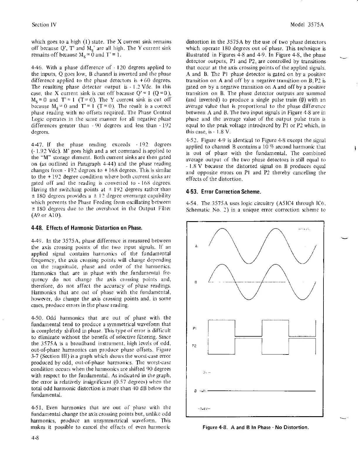
distortion in the
3575A by the use of two
phase
detectors
which operate 180 degrccs out of
phase.
This technique is
llustrated
in Figures
4-8 and 4-9. In Figure
4-8, the
phase
detector outputs, P1
and
P2,
are controlled by transitions
that occur at the a-xis crossing
points
of the
applied signals,
A and
B. Thc
Pl
phase
detector
is
gated
on
by
a
positivc
transition on A ald off
by
a negative transition on
B;Pl is
gated
on
by
a negative
transition
on
A and off by a
positive
transitior
on B. The
phase
detector outputs are
summed
(and
invertcd) to
produce
a
sirgle
pulse
train
((D)
with an
average valuc that is
proportional
to the
phase
difference
between A and B. The two i,rput signals in Figure.l-8 are irl
phase
and the average
value
of
the output
pulse
train is
equal
to the
peak
voltagc
introduced by Pl or P2 which. irr
this casc, is
-
1.8 V.
.1-52.
Figure
4-9
is identical
to
Figure 4-8
except
the signal
applied to channel B
contains
a l0
% second
hartnonic
tlut
is out of
phase
with the
fundamental.
The
combined
avcrage output
(rf
the
two
phase
detectors is
still
equal ro
-
1.8 V because
the distorted signal on B
produces
equal
and opposite
errors
on Pl and P2 thereby cancelling
the
effccts
of the distortion.
4-53.
Error Correction Scheme.
4-54.
The 3575A uses logic circuitry
(A5lC4
through
IC6.
Schernati. No. 2) in a
unique error correction scheme to
a
.e.
Fiqure 4-8. A
and B
ln Phase
-
No Distortion.