Nlodel
-15
75
A
mininlize rhr' efir'cts
of
noise on
phase
readings.
The
follorving porcgr:phs
briefly
describe how noise can
intro-
ducr'errors lnd ho*
these errors are
corrected.
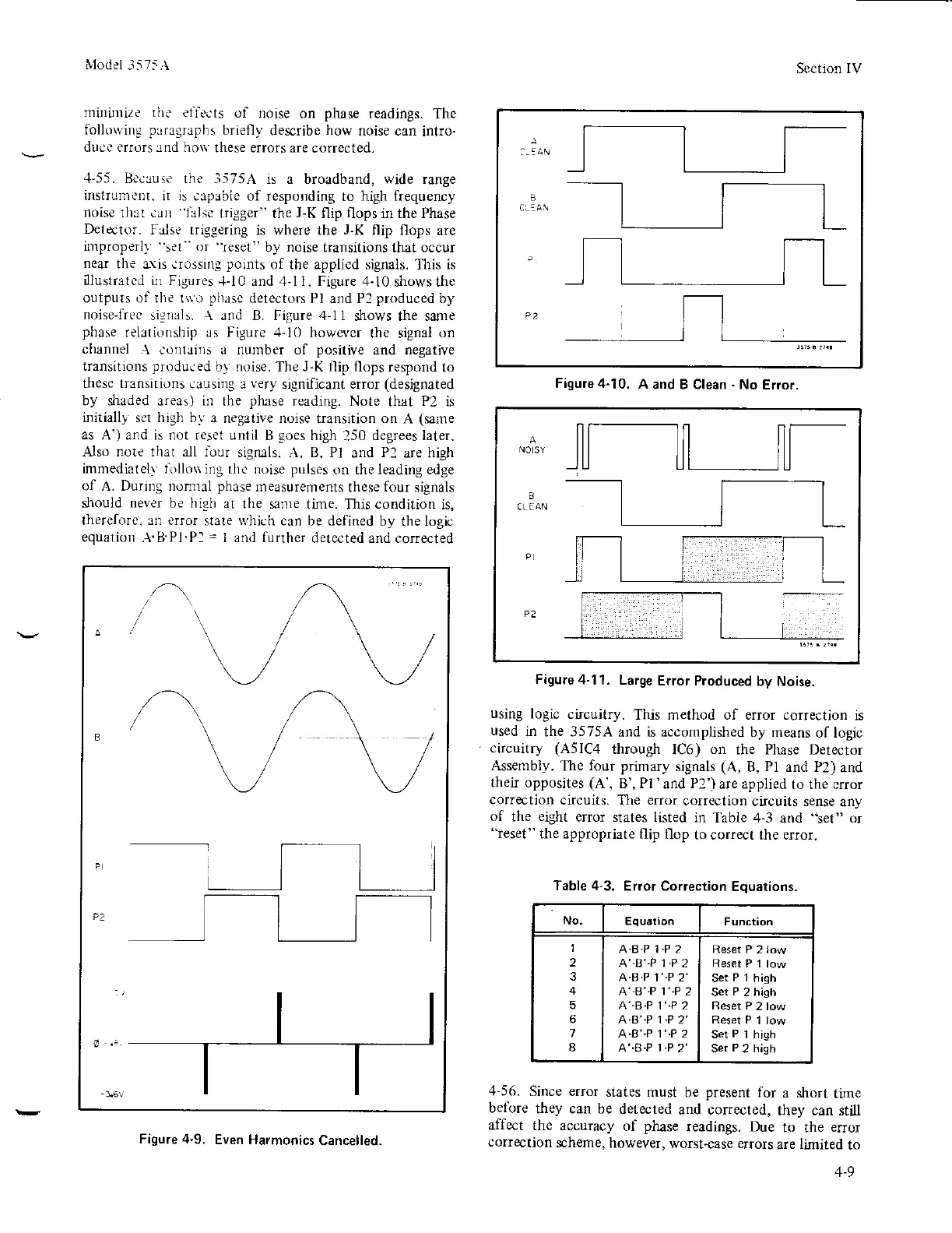
-1'55.
Becuuse the
-1575r\
is a broadband, wide range
instrurnL'nt.
ir is cap3blc of respolding
to high frequency
noise
thal .rn lalse
trigger" the
J-K
flip flops in
the
Phase
Detector.
Fds., trisgering
is where the
J-K
flip flops
are
irnproperl)
set"
or
"reseti!
by
noise
transitions that occur
near
the &\is.rossing
points
of the applicd signals.
This
is
Iustr3tcd ii1 Figures
-1-10
and 4-l 1. Figure
.l-10
shows the
outputs of the t*'o
phasc
detectors
Pl and P2
produced
by
noise-Iree
signals. A and B. Figure 4-11
shows the sane
phase
relationship as
Figure
.+-10
however
the signal
on
channel
A contains a nutnber of
positive
and
negatiye
transitions
produced
by noise.
The
J-K
flip flops respond
to
these transilions
causing a
very
significant error
(designated
by shaded areas) in
the
phase
reading.
Note
that
P2
is
initiall) set high b!' a
negative noise
trarsition on A
(same
as A') and is not reset until
B
soes
high
250
degrees later.
Also note thar all lour
sigruls. A. B, Pl
and
P2
are high
imrnediatel) iillori
ing thc noise
pulses
on the leading edge
of A. During nonrlal
phase
n'teasurements
these
four
signals
should
never
be
high
at
the sanre tine.
This
cotditiorl
is,
thereforc. an crror
stare
rvhich
can be defined
by the logic
equation
.\.B
P1.Pl
=
I and lirther
detected and corrected
Section IV
Figure 4-10.
A
and B Clean
-
No
Eror.
NO
SY
CLEAN
Figure
4-l
l. Large
Error Produced
byNoise.
using
logic
circuitry.
This method of error correction
is
used
in the 35754
and
is
accornplished by rneans
of logic
ctcuitry (A5lC4
through
IC6) on the Phase Detector
Assembly.
The
four
prirnary
signats
(A,
B,
Pl
and P2)
and
thet opposites
(A',
B', Pl 'and P2')
are applied
to the crror
correction
circuits.
The
error
correction
circuits sense
any
of
the
eight
error
states
listed
in
Table 4-3 and "set" or
"reset"
the appropriate
flip flop
to correct the error.
Table 4-3.
Erlor Correction
Equations.
Equation
1
2
3
4
5
6
7
8
A.B.P 1.P 2
A"B"P 1
.P
2
A.B.P
1"P 2'
A'-B'.P
l"P
2
A'.8.P 1"P
2
A.B"P 1.P 2'
A.B"P 1'.P 2
A"B.P 1.P
2'
Reset P
2 low
Set
P t
high
Ser
P
2 high
Reset
P 2 low
Set
P
i high
Sei
P
2
high
.+-56.
Since error
states must
be
present
for
a short
time
before
they can be
detected
and corrected,
they can
still
affect
the accuracy
of
phase
readings. Due
to the
effor
coIIection
scheme, however,
worst-case errors
are limited
to
Figure 4-9.
Even Harmonics
Cancelled.
1-9