Section
IV
a
few
degrees.
This is a vast improvement
over conventional
phase
meters that
give
totally efioneous
readings
in
the
presence
of noise. For
further iniormation concerning the
effects of noise on 35754
phase
readings,
refcr
to
Para-
glaph
3-54.
4-57. Function
Switching Circuits
(A8
Schematic
No.
5).
4-58.
The
Function
Switching Assernbly
(A8)
is comprised
of
four
indiyidual sectiolrs- Eaoh section
performs
a
particular
switching
or logic function in respollse
to
the
front
panel
control
settings.
4-59.
Compensating Circuits
(A8lCl,
lC2,
O1
through
Q6).
The logarithmic outputs
frotn
the
Synchronous
Recti-
fiers
in channels A and B are applied to operational
amplifiers A8lC2 and A8ICI,
respectively.
Note
that
the
gain
of these operational amplifiers is controlled by
thermistors R56 and R57
in
the feedback networks.
The
purpose
of
the thermistors is to change the
gain
of the
operational
amplifiers to cornpensate for dight
gain
valia-
tions that occur in the log
Arnpliliers
due to temperature.
Under normal
conditions, the
gain
of ICI
and
IC2 is
hetween I and l.l.
4-60. Transistors
Ql
through
Q3
and
Q4
tfuough
Q6
at the
outputs of
ICI and IC2 are controlled by the corresponding
voltage range
switch
on
the
front
panel.
When
the channel
B range switch is set to the 2 mV to
20
V
position,
Ql
and
Q3
are conducting
and
Q2
is cut off. When conducting,
Ql
supplies a
I
mA
current
which
produces
a 200
mVdc drop
across R12. This
offsets
the Log B anrplitude reading by
+
20
dB
to compensate
for
the 20 dB sigrBl attenuation
introduced
by the
lnput
Attenuator.
When
the 0.2
mV
to
2V
range is selected,
Ql
and
Q3
are cut off and
Q2
is
switched on. Since the Input Attenuator does not attenuate
the signal on the
lower
range, an offset is
not required.
The
purpose
of
Q2
is to attenuate the signal
slightly
to maintain
equal toading on
both
ranges.
Transistors
Q4
through
Q6
at
the
output of
IC2
operate
in the same manner to corcct
the
lrg
A amplitude reading.
4-61.
Amditude Summing and Function Switching
Cir-
cuits
{A8O7
through 014, lc3). The
outputs of A8lCl and
A8lC2 are
appled
dirertly
to
the function switching
Model 35754
circuits consisting of
AtlQT through A8Q14.
This
circuitry
is controlled
by two
iines,
Ap
(A8
pnrs
8 and Jland
Bp
(AE
pin
9 and
K)
rvhich are connected to the front
panel
AMPLITUDE FUN-CTION
switch
through
the lnterface
Substitution Board
(Al6A)
or the lnterface
Board
(Al6B
.
Optior 001. 00-l).
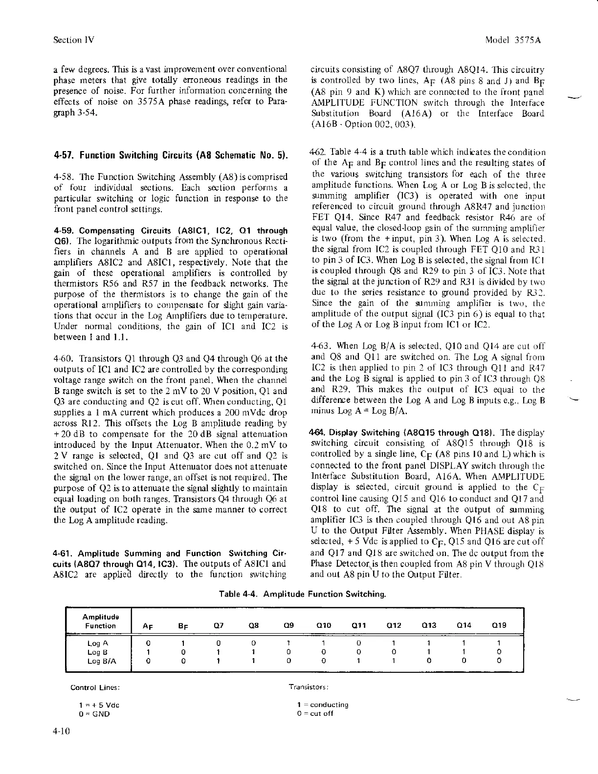
442. Table 4-4 is a truth table which
indtates the condition
of
the AF and BF
control
lines
and the resulting states of
t}le
yarious
switching
transistors
for
each
ol
the three
amplitude
functions.
Whcn
Log
A or
Log B is selected. the
srmming
amplifier
(lC3)
is operated with one inpur
referenced
to circuit
ground
tfuough
A8R47 and
junctiorl
FET
Ql.l.
Since R47 and
feedback resistor
R46 are
of
equal
value,
the closedJoop
gain
of the sumnring
anrplifier
is two
(from
the
+input, pin
3).
When
l,og A is selected.
the signal from
IC2 is coupled through FET
Ql0
and lU1
to
pir
3 of IC3. When
l,og
B
is selected, the signal from ICI
is coupled
though
Q8
and R29 to
pin
3
of
IC3. Note that
the signa.l at thejunction of
R29 and R3l is divided
by two
due
to the series resistance to
gound provided
by R31.
Since the
gain
of
the srnrlling arnplifier is 1wo. the
amplitude
of the output signal
(lC3 pin
6)
is
equal to
rhat
of
the Log A or Log B input from ICI or
IC2.
4-63. When
l,r.lg B/A is
selected,
QlO
and
Ql4
are cut oIf
and
Q8
and
Qll
are
switched
on.
Thc Log A signal
fronr
lC2 is
then applied to
pin
2 ot lC3 through
Ql
I and R.17
and the
ll]g
B
signal
is
applied to
pin
3 of lC3 through
QE
and
R29. This makes
the
output
of lC3 equal
to
the
differerpe
betweer the Irg A and
Log B inputs
e.8..
Log B
minus
log A
=
Log B/A.
zl8l.
Display
Switching
(A8O15
through
018).
The
display
switching
circuit consisting of
A8Q15 through
Ql8
is
controlled by a single
line, Cp
(A8 pins
l0 and
L)
which
is
connected
to
the front panel
DISPLAY
switch through the
lnterface
Substitution Board,
A16A.
When
AMPLITUDE
djsplay is selected, ctucuit
ground
is applied to
the CF
control
line causing
Q15
and
Ql6
to
conduct and
Ql7
and
Qt8
to
cut off.
The signal at the output
of summing
amplifier
IC3 is then coupled through
Ql6
and out A8
pin
U to the
Output Filter Assembly.
When
PHASE
display is
selccted,
+
5 Vdc is applied to
Cp,
Q15
and
Ql6
are cut ofl
and
Ql7
and
Ql
8 are switched on.
The dc output
fron
the
Phase
Detecto(.is
then coupled
from
A8
pin
V tluough
Ql8
and out
A8
pin
U to
the Output Filter.
Table 4"4. Amplitude Function
Switching.
Amplitude
AF
BF
A7 Oa
Og OIO
O11 A12
O13 O14 O19
Log
A
Log B
Los B/A
111
110
ooo
01001'l
01
't0110000
00110011
Conrrol Lines:
1=+5Vdc
O-GND
1
=
conducting
4-10