Section V
5.5. PEBFOBMANCE CHECKS.
5-6.
The
following
performance
checks are in{abinet
procedures
that
can be used to verify that the Model
3575A
meets the specifications listed in Table
1-1.
These
proce-
dures
can
be used for
incoming
quality
control inspection,
to
check specifications after a
repair or
for
routine
maintenance.
5-7. Test Card.
5-8. A Performance Check Test Card
is
provided
at the
end
of this section
for
your
convenience
in
recording the
performance of the Model 35754 during
performance
checks, This card can be
removed from the manual and
used
as
a
permanent record of
the
incoming inspection
or
of a routine
performance
check. The test
card may be
reproduced
without written
permission from
Hewlett-
Packard.
$9.
Panel Meter Accuracy Check.
5-10.
The
purpose
of this check is to
yerify
that
the
panel
meter accuracy is within the
i
3 count
(1
0.3
dB,
t
0.3
deg.) tolerance listed in Table 1-1.Ifthe
panel
meter
fails to
meet the required specifications,
perform
the
Panel
Meter
Accuracy Adjustments
(Paragraph
5-29) before
pro-
ceeding with the other
perforrnance
checks
in
this
section.
RTCOMMENDED TEST EQUtrMENT:
DC Digital
Voltmeter
(-hp-
Model 3450A)
Frequency Synthesizer
(hp-
Model
3320B)
Variable Attenuator
(-hp-
Model 355D)
(2)
50-Ohm Feed-Thru Terminations
(hp-
Model
l 1048C)
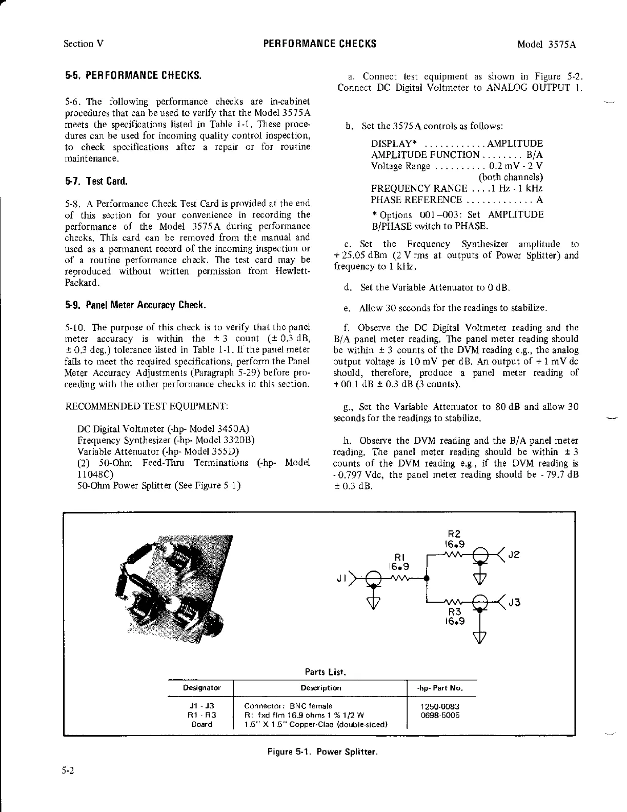
50-Ohm Pow
Splitter
(See
Figure 5-l)
a. Connect test equlpment
Conneot DC Digital Voltmeter
Model
35754
as shown in Figure 5-2.
to ANALOC OUTPUT 1.
b.
Set the
3575A controls
as
follows:
DISPLAY* . .. AMPLITUDE
AMPLITUDE
FUNCTION. .. . .. . . B/A
Voltage Range -
0.2 mV
-
2 V
(both
channels)
FREQUENCY RANGE ....l
[lz
-
1kIlz
PHASEREFERENCE ........,.... A
*
Options
U01
003:
Set
AMPLITUDE
B/PHASE
swilch
to
PHASE.
c.
Set the
Frequency
Synthesizer amplitude to
+
25.05 dBm
(2
V
rms
at outputs of Power
Splitter) and
frequency
to I kl1z.
d. Set the Variable
Attenuator to 0
dB.
e.
Allow
30 seconds
for
the
readings to
stabilize.
f. Observe the DC Digital Voltmeter reading and the
B/A
panel
meter reading.
The
panel
meter reading should
be within
t
3 caunts
of
the
DVM reading e.g.,
the analog
output voltage
is 10
mV
per
dB.
An
output of
+
I mV dc
should, therefore,
produce
a
panel
meter reading
of
+
00.1 dB
t
0.3 dB
(3
counts).
9.,
Set
the Variable
Attenuator
to
80
dB and allow 30
seconds
for
the
readings
to stabilize.
h.
Observe the
DVM reading
and the B/A
panel
meter
reading.
The
panel
metff
reading
should
be within
t
3
counts of
the
DVM reading e.g., if the DVM reading is
-
0.797
Ydc, the
panel
meter
reading
should be
-
79.7
dB
r 0.3 dB.
PEBFOBMANCE CHECKS
Parts
Lisr.
Designator
-hp-
Part No.
Jl
,J3
R1
.R3
Eoard
Connector: BNC
lemale
R I
f
xd flm 16.9 ohms
'l
1.5"X1.5"Copper-Clad
%112W
(double'sided)
1250-0083
0698-5005
Figure 5-1. Power
Splitter.