Model 3575A
i.
Without disturbing
the 3575A
or test
equipment
control settings,
reverse the
inPut connections
to the
3575A so
the Variable Attenuator
is connected
to Channel
A
and the
Powff Splitter is co[n€cted
to Channel
B. A]low
30 seconds
for
the
readings to stabilize.
j.
Observe the
DVM
reading and the B/A
Panel
meter
reading. The
panel meter reading should
be within
!
3
counts
of.
the
DVM
reading e.g., if the DVM
reading is
+
0.802
Vdc, the
panel
meter reading should
be
+
80.2
dB
1
0.3 dB.
k, Options
001-{03:
Perform the
following additional
steps to
verify the accumcy
of the riglrt-haad
(phase)
panel
meter.
l.
Ccnnect
the
DC Digital Voltmetff
to ANALOG
OUTPU I 2.
m. s€t the Variable Attenuator to
0 dB and allow 30
seconds
for the
readings to stabilize.
n.
Observe
the DVM
reading
and
the
right-hand
panel
meter reading. The
panel
meter
reading strould be within
t
3 counts
of
the
DYM reading.
o. Set the PHASE
REFERENCE switch to the
-
a
position
and
allow 30 seconds
for
the
readings
to stabilize.
p.
Observe the
DVM reading and tne right-hand
panel
meter reading.
The
panel
meter reading should be within
t
3 counts of the
DVM r€ading.
Sll.
Amplitrde 8rd Phase Accuracy
Checkr
5-12. The
purpose of
these checks
is to veriry that the
3575A meets the anplitude and
phase
acturacy specifi-
cations listed in Tabte l-1.
Read Section
III,
Paragraphs
3-13 to 3-16 before
performing
the
following tests. If
the
3575A fails to
meet any of the
required
specifications,
perform
the
adjustments outlined
in
Paragraphs 5-25
through
5-46.
NOTE
The
checks
outlined in the
following
procedure
will veily
the
3575A
phase
accutscl
at 0 degees and
180 degrees at
citical levels and
frequencies
throughout the operating
mnge of the
instrument. Satisfactory
petormance
duing
these checks is reasonable
verifrcation thst
the
phase
detector circuits are operating
properly.
Moginal
perfor'
mance, however, may rellect a
misadiustment
or mal'
function
that could degrade
the overall
performtnce
and
produce
rcadings that are
out of tolerance at
points
other
than 0 degees
and 180 degrees.
If
performance
tppeos
marginal or if
further
verification of
phtse
accuracy is
desired,
"spot
check" the 45 degree
points
andlor
the
90
deglee
paints
using a
precision
ph$e generator or
reler to
the Supplemental
Phase Accuracy Check outlined in
Poc
e1@h 5-
17.
RECOMMENDED TEST EQUIPMENT:
Frequency
Slnthesiza
(-hp- Model 33208)
Variable Attenuator
(-hp-
Model 355D)
(2)
sCOtun
Feed-Thnr Termtuations
(-hp-
Model
l1048c)
50-Ohm Pows
Splitter
(See
Figure
5-1)
(l)
48"
50-Ohm
Cable with
BNC
connectors
(-hp-
1 l l70c)
(2)
24"
500hm
Cables with
1r 1708)
(l)
9"
50-Ohm
Cable
with
t0s02A)
BNC connectors
(-hp-
BNC connectors
(-hp-
PERFORMANGE
CHECKS
Section
V
FREOUENCY SYNTHESIZER
hp 332oa
Mto M
CONNECTOR
hp t25o-ozt6
IOdB /
STEP
ATTEN UATOR
,p
3s5D
(T..hindle
oi 3575A
for frequenaies >lMHz,
lerminole ot ottenuoior
fo. f.equencies SIMHd
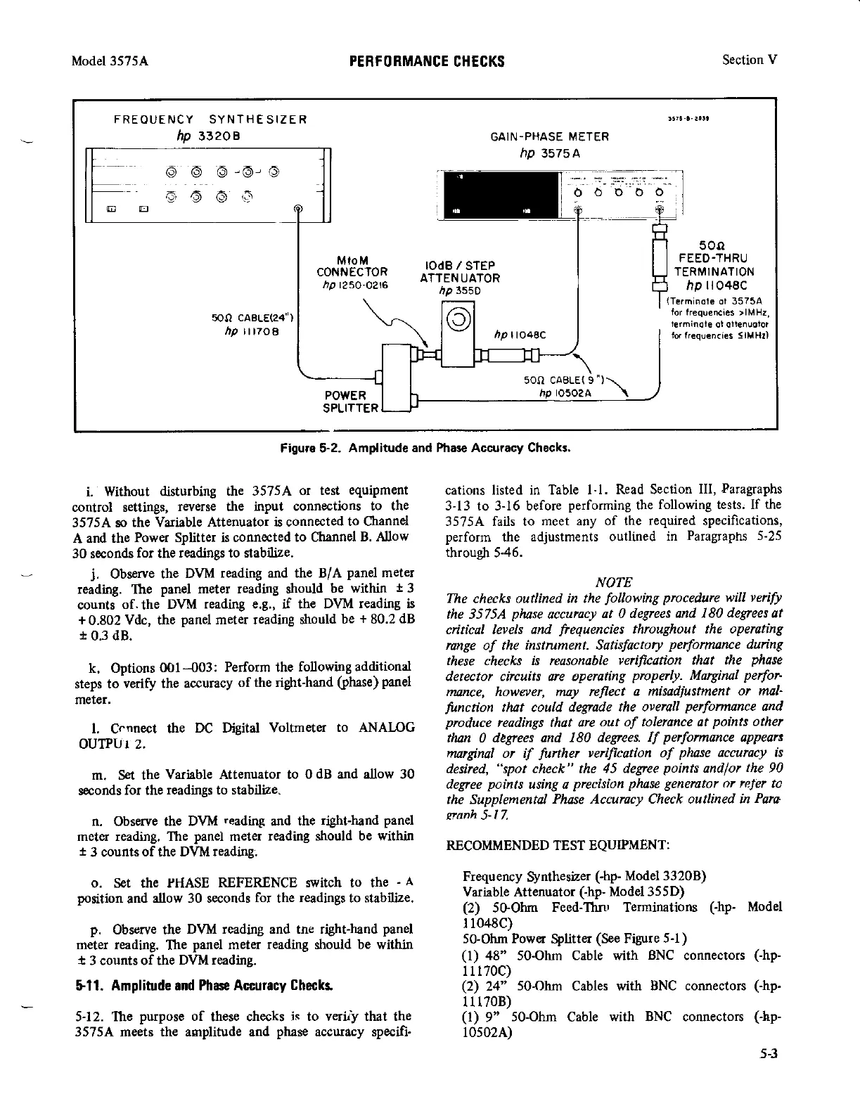
Figure $2.
Amplitude and Phale Accarracy Checks.
5-3