Chapter 3 Replacing Assemblies
To Remove A4 AC Power Supply Assembly
3-16 Assembly-Level Service Guide
3
3 Remove the two TORX screws (H2) on the rear panel using the
TORX 10 screwdriver as shown in Figure 3-9.
4 Lift up A4 AC Power Supply Assembly and disconnect its cable
from J18 on A1 Motherboard Assembly to remove the power
supply assembly as shown in Figure 3-9.
NOTE
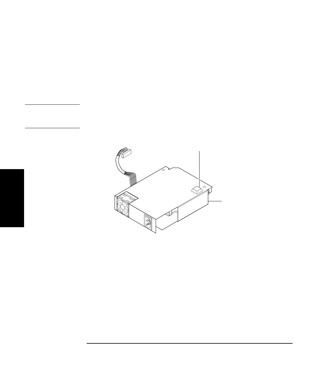
When replacing the power supply, order the rubber foot (0403-0424).
Figure 3-10 shows where the rubber foot is located on the defective
assembly.
Figure 3-10. Location of the Rubber Foot
5 If the Counter contains the Option 002 DC Power Input Assembly,
disconnect A4 AC Power Supply’s other cable from Option 002 as
shown in Figure 3-11.
Rubber foot
A4 AC Power
Supply Assembly