Do you have a question about the HP 652A and is the answer not in the manual?
Warranty excludes defects from improper maintenance, misuse, or unauthorized modification.
Buyer's sole and exclusive remedies are provided herein; HP not liable for consequential damages.
Connect instrument chassis and cabinet to an electrical ground to minimize shock hazard.
Do not remove covers; internal adjustments by qualified personnel only. Disconnect power.
Do not attempt internal service or adjustment unless another person capable of first aid is present.
Do not install substitute parts or perform unauthorized modifications due to hazard introduction.
Warnings precede potentially dangerous procedures; follow instructions in warnings.
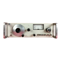
HP Model 652A is a stable, capacitance-tuned oscillator with 10 Hz to 10 MHz frequency range.
Accessory furnished is the HP Model 11048C Feedthrough Termination for impedance matching.
Identifies instrument serial number structure (prefix and suffix) and country of manufacture.
Covers installation/shipping info, and initial mechanical/electrical inspection procedures.
Details power source requirements (115/230V) and grounding recommendations for personnel safety.
Covers general installation, cooling requirements, and rack/bench mounting conversion.
General guide for repackaging for shipment, including contact for questions.
Overview of maintenance and service information provided in this section.
Identifies and describes the function of all front and rear panel controls, connectors, and indicators.
Procedure to properly zero-set the output monitor for maximum accuracy and mechanical stability.
Step-by-step procedure for operating the 652A Test Oscillator, including setting controls and connecting loads.
Describes instrument blocks (oscillator, amplifier, monitors) and general circuit principles.
Explains the oscillator circuit, including the Wien bridge network and frequency selection.
Details power amplifier, normal monitor, and expand monitor circuits for signal amplification and monitoring.
Describes how the output attenuator reduces signal level at the 50-ohm and 600-ohm output connectors.
Explains the regulated power supply providing all DC voltages required by the 652A circuits.
Overview of maintenance and service information provided in this section.
Lists the necessary equipment, specifications, and recommended commercial test instruments.
In-cabinet tests to ensure the Model 652A operates within specifications for inspection and repair.
Complete procedure for adjusting and calibrating the Model 652A if performance tests fail.
Procedures to help isolate malfunctions, to be used after calibration attempts fail.
Overview of circuit diagrams, block diagram, and schematic details in this section.
Explanation of terms and symbols used as reference designators in circuit diagrams.
Overview of information provided for ordering replacement parts.
Instructions for obtaining replacement parts, including order address and required info.
Information required when obtaining a part that is not listed in the manual.
| Brand | HP |
|---|---|
| Model | 652A |
| Category | Power Tool |
| Language | English |