Do you have a question about the HP 654A and is the answer not in the manual?
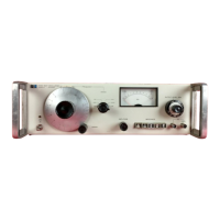
Overview of the Hewlett-Packard Model 654A Test Oscillator's purpose and features.
Details frequency range, level flatness, and accuracy specifications.
Lists optional accessories recommended for use with the instrument.
Procedure for inspecting the instrument upon receipt for damage and completeness.
Specifies operating voltage and frequency ranges for the instrument.
Details safety grounding procedures for personnel protection.
Identifies and describes front panel controls and connectors.
Step-by-step guide for powering on the instrument correctly.
General steps for operating the test oscillator for measurements.
Front panel checks to ensure correct operation before use.
Provides an overview of the Model 654A's architecture and function.
Explains the Wien Bridge frequency adjustable oscillator circuit.
Details the function and role of the buffer amplifier stage.
Explains the ALC system and amplitude control operation.
Describes the function and operation of the amplitude control integrator.
Explains the function, range, and steps of the attenuator system.
Describes the design and function of the power supply circuits.
General overview of in-cabinet performance tests.
Procedure to check the accuracy of the frequency range settings.
Verifies frequency accuracy against specified tolerances.
Specific procedure to check amplitude accuracy for 50 ohm output.
Procedure to check output level flatness for 50 ohm output.
Checks the accuracy of the meter tracking function.
Verifies the accuracy of the 10dB attenuator steps.
Introduces procedures for checking the output signal balance.
Procedure for measuring harmonic distortion levels.
Procedure to measure unwanted hum and noise levels.
Adjusts the output voltages of the regulated power supplies.
Introduces the process for calibrating frequency settings.
Adjusts the feedback loop for optimal oscillator performance.
Procedure to adjust distortion levels to meet specifications.
Adjusts the meter range for proper calibration.
Calibrates the amplitude control and meter indication.
Calibrates amplitude accuracy across various impedance settings.
Introduces procedures for balancing the output signal.
Introduces procedures for adjusting output level flatness.
Adjusts the output level flatness for 75 ohm impedance.
Overview of procedures for isolating malfunctions.
Initial troubleshooting steps performed on the front panel.
Provides a systematic method for fault isolation using a flow chart.
Guides on troubleshooting power supply circuit issues.
Procedures for diagnosing and fixing oscillator circuit faults.
Guides on troubleshooting the buffer amplifier stage.
Procedures for diagnosing balanced amplifier circuit faults.
Isolating faults within the ALC loop components.
Guides on troubleshooting issues with the attenuator circuits.
Rules and precautions for working on circuit boards.
Procedures for servicing the rotary switches.
Instructions for servicing the tuner assembly components.
Adjusts the frequency dial and 1K range for accuracy.
Adjusts tracking for specific frequency ranges.
Adjusts the X1M frequency range for accuracy.
Adjusts the X100K frequency range for accuracy.
Adjusts the meter range for proper calibration.
Calibrates amplitude accuracy across all impedance settings.
Introduces procedures for balancing the output signal.
Introduces procedures for adjusting output level flatness.
Test for frequency range verification.
Tests the accuracy of frequency settings.
Checks amplitude accuracy across impedances.
Tests the flatness of the output level.
Verifies the accuracy of the meter tracking function.
Checks the accuracy of the attenuator steps.
Verifies the balance of the output signal.
Measures harmonic distortion levels.
Checks for unwanted hum and noise.
Verifies the counter output signal.
Overview of the replaceable parts section.
Instructions on how to order replacement parts.
Information on obtaining parts not found in the list.
Overview of the circuit diagrams section.
Describes the content of the diagrams.
Explains schematic symbols and terms used.
Details specific component changes for earlier serial numbers.
Details specific component changes for earlier serial numbers.
Details specific component changes for earlier serial numbers.
| Brand | HP |
|---|---|
| Model | 654A |
| Category | Power Tool |
| Language | English |