Procedure 6.
A6 Power Supply Assembly
6. Ensure that all cables are safely routed and will not be damaged when securing the A6
cover.
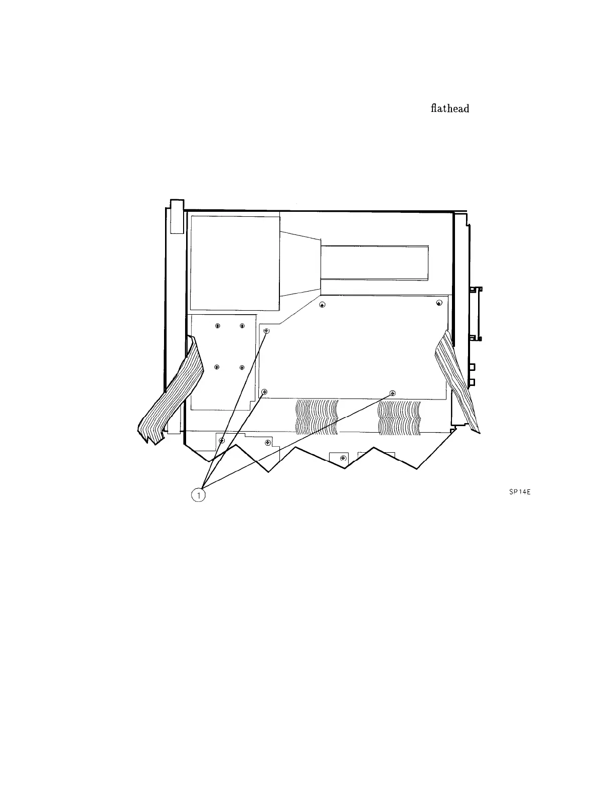
7. Secure the power supply cover shield to the power supply using three
flathead
screws (1).
See Figure 4-12. One end of the cover fits into a slot provided in the rear frame assembly.
Ensure that the extended portion of the cover shield is seated in the shield wall groove.
8. Fold the A2, A3, A4, and A5 assemblies into the spectrum analyzer as described in
“Procedure 5. A2, A3, A4, and A5 Assemblies Replacement,” steps 6 through 12.
Figure 4-12. Power Supply Cover
SP14E
4-24 Assembly Replacement