11. Monitor A3U401B pin 7
(LIF-STB)
with
an oscilloscope or logic probe. This is the strobe
for the A5 IF assembly.
12. Press
(AMPLITUDE]
and check that pulses occur when toggling between
REF‘
LVL settings of
-10
dBm
and -20
dBm.
13. Monitor A3U401B pin 9
(LLOGSTB)
with an oscilloscope or logic probe. This is the
strobe for the A4 log amplifier/Cal oscillator assembly.
14.
Press
(Wj
and check that pulses occur when toggling between
LINEAR
and
Lac
mfm.
Interface
Strobe
Select
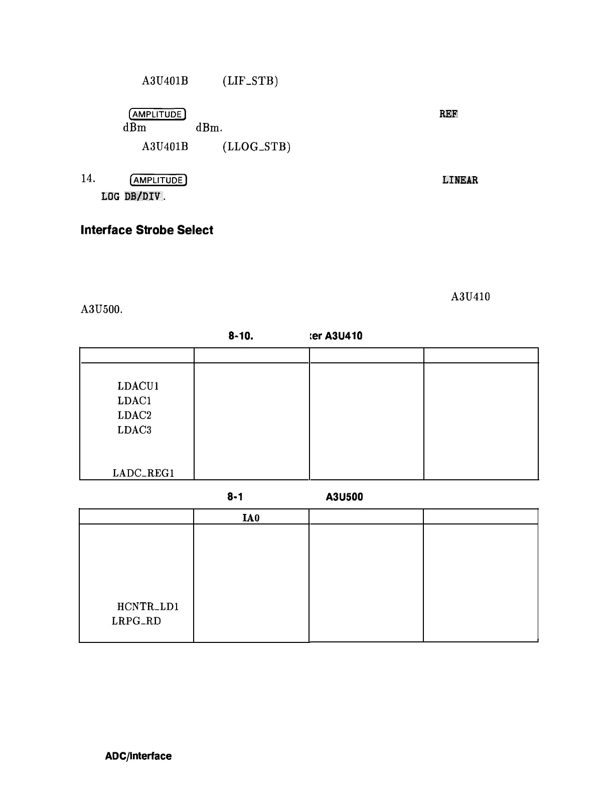
Refer to function block K of A3 Interface Assembly Schematic Diagram in the
HP 8560 E-Series Spectrum Analyzer Component Level Information.
Interface strobe select generates the various strobes used by circuits on the A3 Interface
Assembly. Table 8-10 and Table 8-11 are the truth tables for demultiplexers A3U410 and
A3U500.
Table 8-10. Demultiple
:er
A3U410 Truth Table
Selected Output Line
IA1
Pin 15, LSCAN-KBD
L
Pin 14,
LDACUl
H
Pin 13, LDACl
L
Pin 12,
LDAC2
H
Pin 11,
LDACS
L
Pin 10
H
Pin 9, LTIMER
L
Pin 7, LADC-REGl
H
Table
8-l
1. Demultiple
Selected Output Line
IA0
Pin 15, LSENSE-KBD
L
Pin 14, LINT-PRIOR
H
Pin 13, LADC-DATA1
L
Pin 12, LDAC-DATA0
H
Pin 11, HCNTR-LDO
L
Pin 10, HCNTR-LDl
H
Pin 9, LRPG-RD
L
Pin 7, LADC-REGO
H
IA2 IA3
L L
L
L
H
L
H L
L
H
L H
H
H
H H
:er A3U500 Truth Table
IA1 IA2
L L
L L
H
L
H
L
L
H
L
H
H
H
H
H
8-30
ADC/lnterface
Section