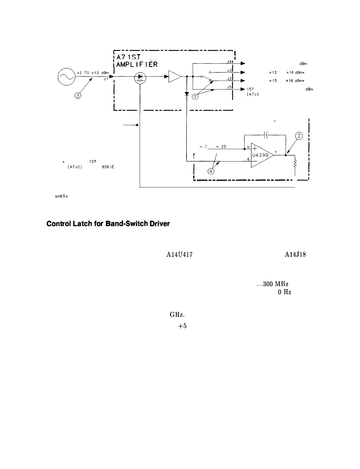
!A7
1ST
LO DISTRIBUTION
!
All
YTO
~AMPLIFIER
J41
J3I
J2
F
SAMPLER OUT -9 TO -2
dBn
HI BAND
+13
TO
f16
d&n:
J5
I
LO BAND
+13
TO
+16
d&n*
I
1ST LO OUT 14.5 TO 18.5
d&n
(A7J3
FOR HP 8561E)
AS V INCREASES
-
A7 OUTPUT INCREASES
I
ONLY ONE
IST
MIXER OUT
(A7J2)
FOR HP
8561E.
I
I
--mm---
SCHEMAT I C
3 OF 5
------------------
‘P/O Al4 FREQUENCY
I
CONTROL
I
I
I
REF VOLTAGE
-.l
TO
-.25
VOLT
I
-e--e----------w
-i
sm66e
Figure 12-3. A7 First LO Distribution Amplifier Drive
Control
Latch
for
Band-Switch
Driver
Refer to function block P on Al4 Frequency Control Schematic Diagram (sheet 3 of 5) in the
HP 8560 E-Series Spectrum Analyzer Component Level Information.
1. Connect the positive lead of a DVM to A14U417 pin 14 and the negative lead to A14J18
pin 6.
2. Set the HP 85623 to the following settings:
Center frequency . . . . . . . . . . . . . . . . . . . . . . . . . . . . . . . . . . . . . . . . . . . . .
..300MHz
Span . . . . . . . . . . . . . . . . . . . . . . . . . . . . . . . . . . . . . . . . . . . . . . . . . . . . . . . . . . . . . OHz
3. The voltage should measure approximately 0 Vdc (TTL low).
4. Set the HP 85623 center frequency to 3 GHz.
5. The voltage should measure approximately
f5
Vdc (TTL high).
12-12 RF Section